Radio frequency security system, method for a building facility or the like, and apparatus and methods for remotely monitoring the status of fire extinguishers

a radio frequency security and radio frequency technology, applied in frequency-division multiplexes, safes, instruments, etc., can solve problems such as indicating a possible security risk occurrence, and the initial installation of ceiling tile clips

Inactive Publication Date: 2006-07-25
BATTELLE MEMORIAL INST
View PDF77 Cites 120 Cited by
  • Summary
  • Abstract
  • Description
  • Claims
  • Application Information

AI Technical Summary

Benefits of technology

[0033]The tamper-indicating device is placed in a security risk detecting position by operatively engaging the tamper-indicating device to two of said components, at least one of which is a security-sensitive component. The two components are characterized in that relative movements between the two components indicates a possibility of a security risk occurrence. The tamper-indicating device is arranged and connected to the two components so that relative movement between the two components causes a break or damage to the tamper-responsive section to cause the tamper-responsive section to go to its non-intact condition.
[0034]Then a signal receiving device is operated to ascertain either a reception of a signal or a lack of reception of a signal from the tamper-indicating device to ascertain the possible security risk oc

Problems solved by technology

”, there is one type of security problem where there is a security-sensitive area where the surrounding walls are not true floor to true ceiling walls, but extend only partially toward the true ceiling.
Also (as indicated earlier in this text), in the prior art where that area with the false ceiling tiles is security-sensitive, in many instances the use of ceiling tile clips is required to be installed in the ceiling system.
Both the initial installation of the ceiling tile clips and the regular visual inspection are costly.
Also, if a covert intrusion has occurred, it may be many hours later that the visual inspection is made.
Thus, the transceiver/monitoring apparatus would recognize that no response was given to that inte

Method used


Image

  • Radio frequency security system, method for a building facility or the like, and apparatus and methods for remotely monitoring the status of fire extinguishers
  • Radio frequency security system, method for a building facility or the like, and apparatus and methods for remotely monitoring the status of fire extinguishers
  • Radio frequency security system, method for a building facility or the like, and apparatus and methods for remotely monitoring the status of fire extinguishers

Examples


first embodiment

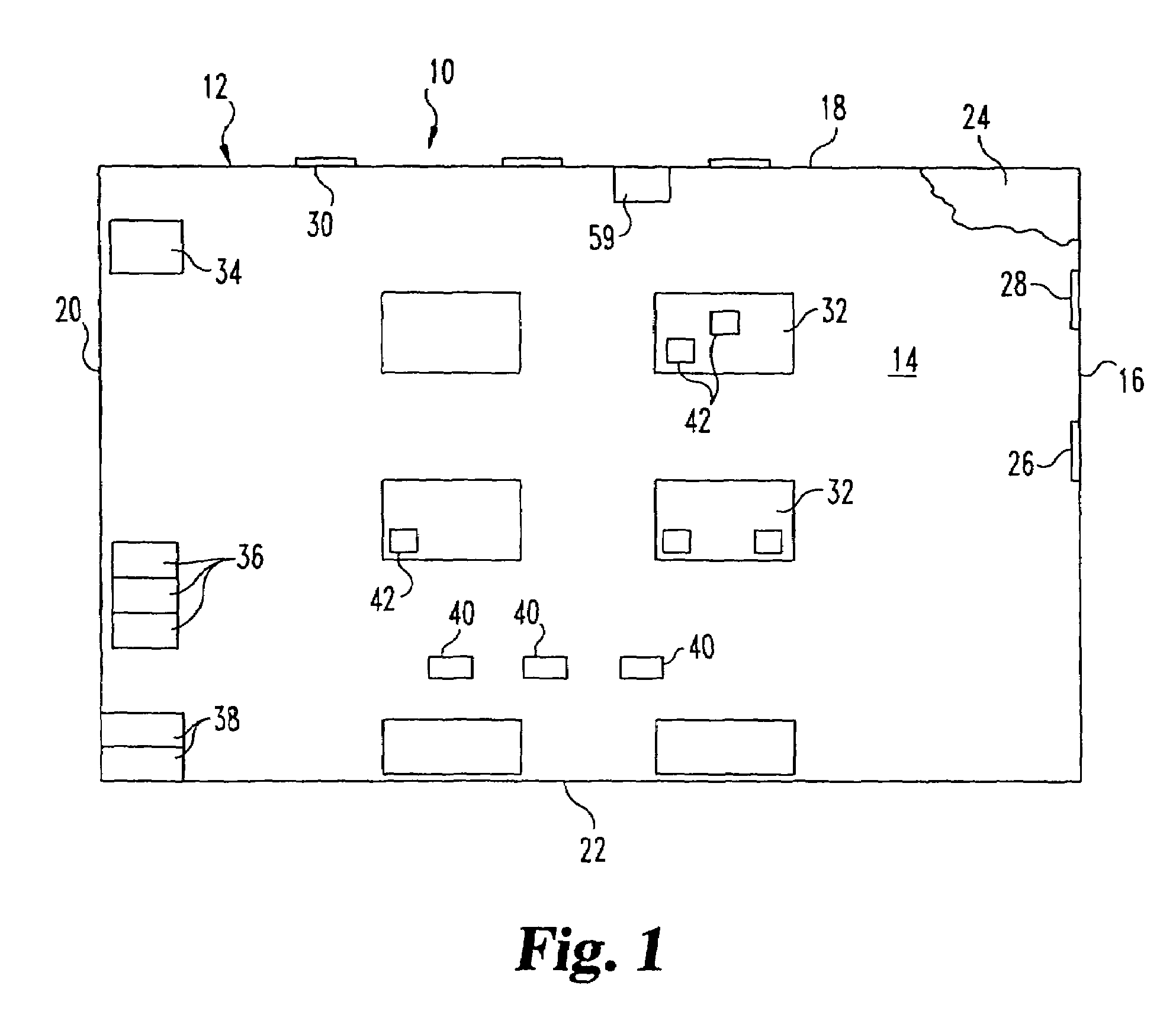
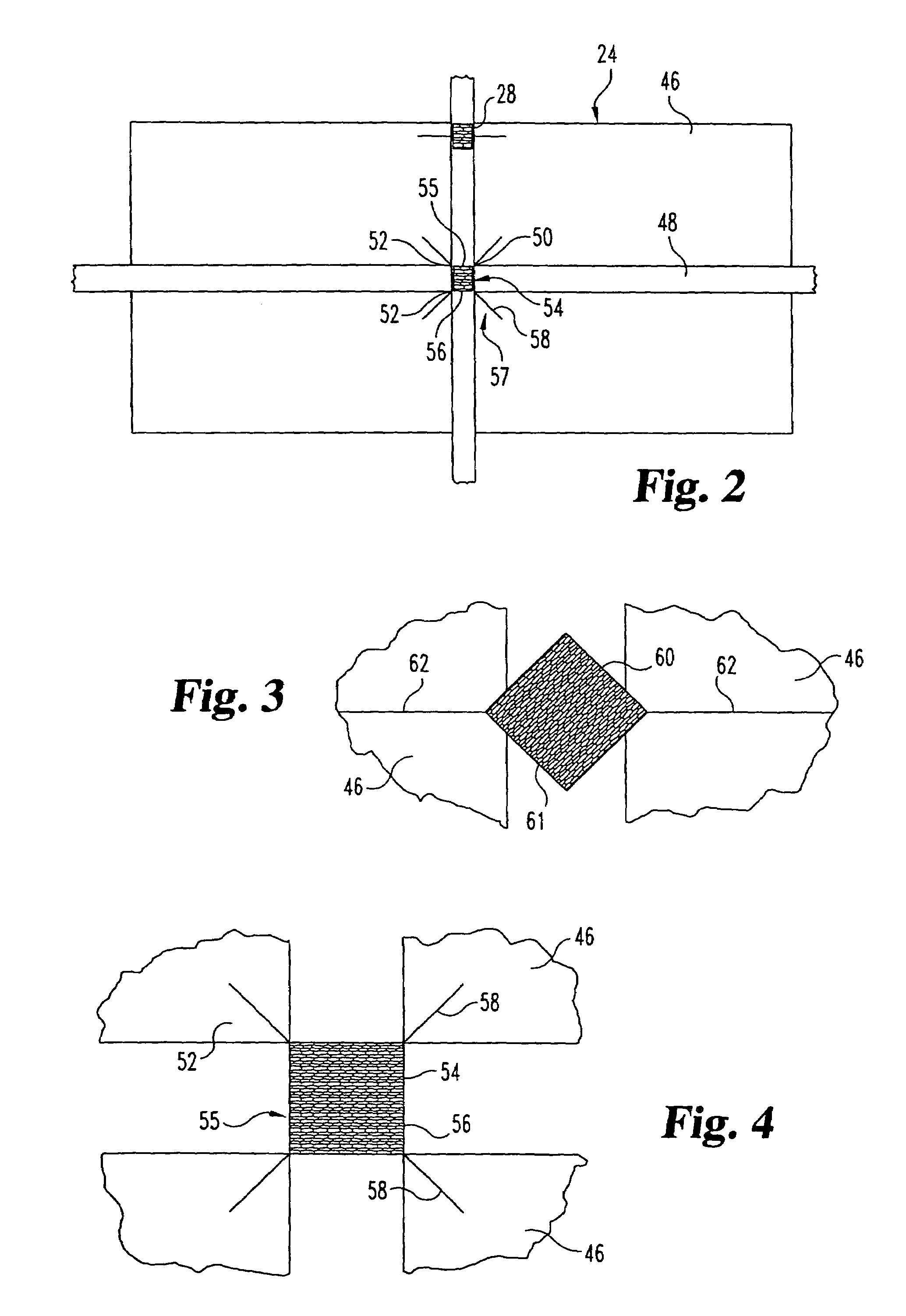
[0075]To describe now this first embodiment reference is first made to FIG. 2 which shows a portion of the aforementioned false ceiling 24, and specifically there is shown in FIG. 2 four of the individual ceiling tiles 46 supported by the support members formed in a rectangular grid pattern, these support members being indicated schematically at 48. Depending upon the size of the area of the false ceiling 24, there could be as many as several hundred tiles 46. These are arranged in a rectangular grid pattern, and the four tiles 46 that are shown in FIG. 2 are arranged in such a configuration, so that there is a juncture location 50 at which four adjacent corners 52 of the tiles 46 meet are closely adjacent to one another.

[0076]In accordance with the present invention, there is located at each of these juncture locations 50 a tamper-indicating device 54. This device 54 incorporates basic RFID technology, and in this particular embodiment comprises an operating or transmitting section...

second embodiment

[0091]Accordingly, only those components of the second embodiment shown which function somewhat differently or are in a somewhat different arrangement are illustrated in 6A.

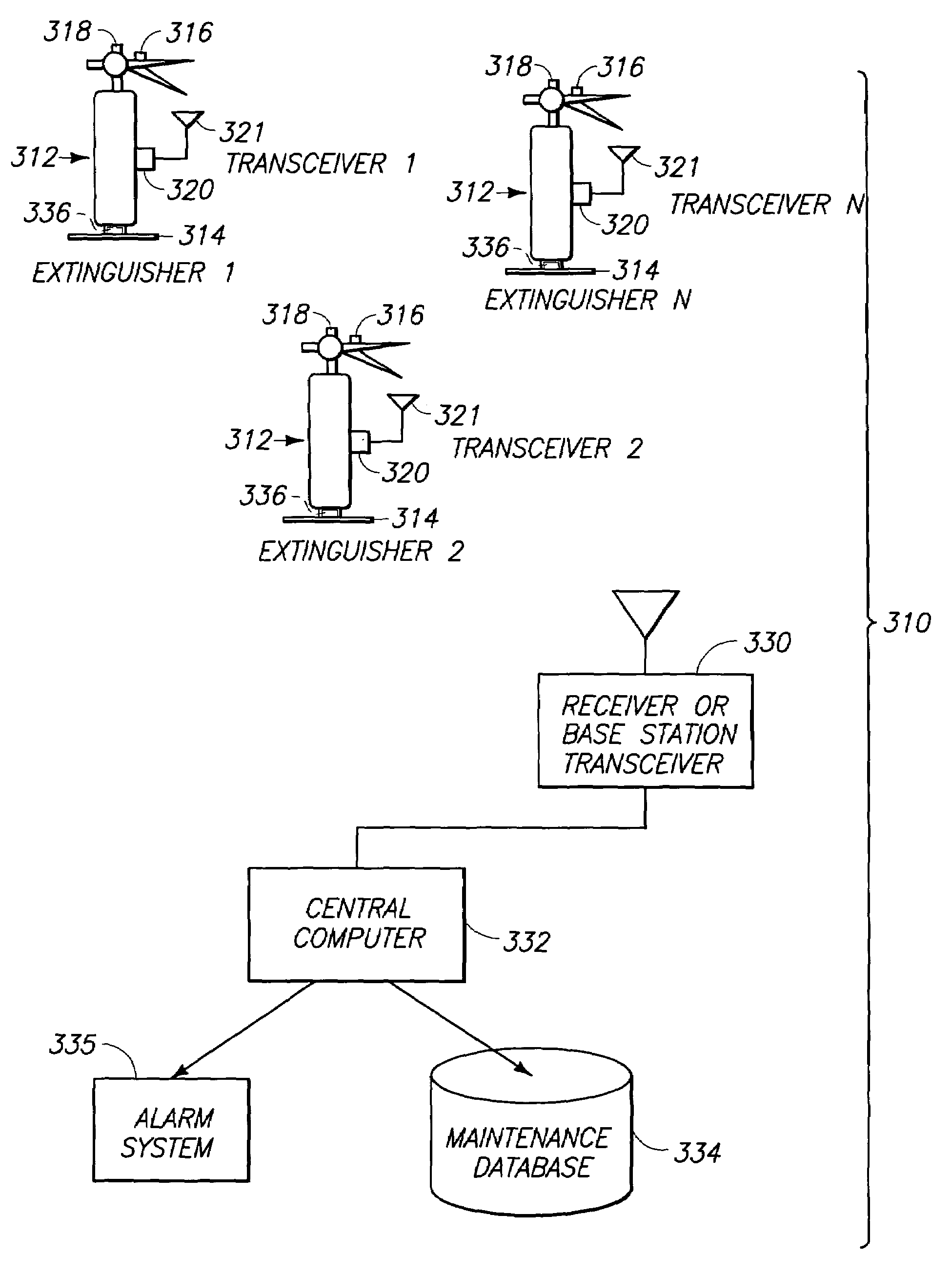
[0092]In FIG. 6A, there is the connection 76a to the micro-controller (68 in FIG. 5), and there is also the voltage source 79a which connects to the connection 76a through the high resistance resistor 78a. However, instead of having the frangible wire 80, there is provided a thermistor 92a connected to the connection 76a and to the ground connection 82a. This thermistor 92a normally is conductive, but if the ambient temperature rises above a predetermined level, the electrical resistance increases. Accordingly, this will initiate a signal to the micro-controller 68 which will in turn transmit an alarm signal that there is a high temperature condition at the thermistor 92a, this high temperature condition possibly resulting from a fire.

[0093]In FIG. 6B, there is shown a third embodiment, and as in the description ...

third embodiment

[0095]This third embodiment could be used in a variety of situations, and these are discussed further later in this text. However, to give one example at this time, the light sensitive surface of the photoresister could normally be covered by an opaque cover in an environment where there is light. The security intrusion or movement of security-sensitive item would result in the opaque cover being removed from the light sensitive surface, thus triggering an alarm.

[0096]FIG. 6C shows a fourth embodiment, and components of this fourth embodiment which are similar to prior embodiments will be given like numerical designations with a “c” suffix distinguishing those in the fourth embodiment. This RF tag 54 of the fourth embodiment is substantially the same as the third embodiment of FIG. 6B, except that in place of the photo transistor 94b, there is provided a magnetic reed switch 96c which is normally open. Then when the switch 96c comes in proximity to a source 97c of a magnetic field, ...


PUM


Abstract

A system for remotely monitoring the status of one or more fire extinguishers includes means for sensing at least one parameter of each of the fire extinguishers; means for selectively transmitting the sensed parameters along with information identifying the fire extinguishers from which the parameters were sensed; and means for receiving the sensed parameters and identifying information for the fire extinguisher or extinguishers at a common location. Other systems and methods for remotely monitoring the status of multiple fire extinguishers are also provided.

Description

CROSS REFERENCE TO RELATED APPLICATION[0001]This is a continuation-in-part of U.S. patent application Ser. No. 09 / 940,142, filed Aug. 23, 2001 U.S. Pat. No. 6,646,550, naming as inventors Wayne M. Gunter, Larry Runyon, and Ronald W. Gilbert, and which is incorporated herein by reference.GOVERNMENT RIGHTS[0002]This invention was made with government support under contract number DE-AC0676RLO1830 awarded by the U.S. Department of Energy. The Government has certain rights in the invention.TECHNICAL FIELD[0003]Aspects of the invention relate to a system, method and apparatus for maintaining security, and more particularly for maintaining security in an environment such as a building facility where there is a security-sensitive area with security-sensitive objects or items. Other aspects of the invention relate to fire extinguishing systems and methods, and to sensing, monitoring, and remote transmitting apparatus and methods used in connection with fire extinguishing equipment.BACKGROUN...

Claims


Application Information

Patent Timeline
IPC IPC(8): G08B13/00E05G1/10G08B13/12
CPCG08B13/126E05G1/10
Inventor RUNYON, LARRYGUNTER, WAYNE M.GILBERT, RONALD W.
Owner BATTELLE MEMORIAL INST
Why Eureka
Try Eureka