Light guide plate with embossments and backlight system using the same

a technology of embossing and light guide plate, which is applied in the field of backlight system, can solve the problems of reducing the optical performance of the backlight system b>100/b>, adding to the cost of raw materials and manufacturing, and achieve the effect of reducing the optical loss of the backlight system and manufacturing at low cos

Inactive Publication Date: 2006-07-25
HON HAI PRECISION IND CO LTD
View PDF10 Cites 31 Cited by
  • Summary
  • Abstract
  • Description
  • Claims
  • Application Information

AI Technical Summary

Benefits of technology

[0009]It is therefore an objective of the present invention to provide a light guide plate

Problems solved by technology

However, the diffusion plate 120 is an extra element that adds to costs of raw materials and co

Method used


Image

  • Light guide plate with embossments and backlight system using the same
  • Light guide plate with embossments and backlight system using the same
  • Light guide plate with embossments and backlight system using the same

Examples


Embodiment Construction

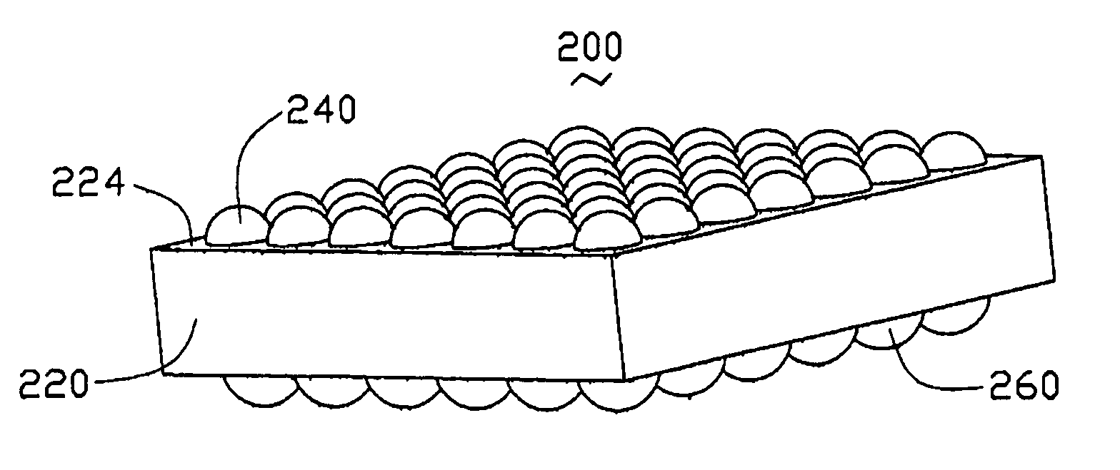
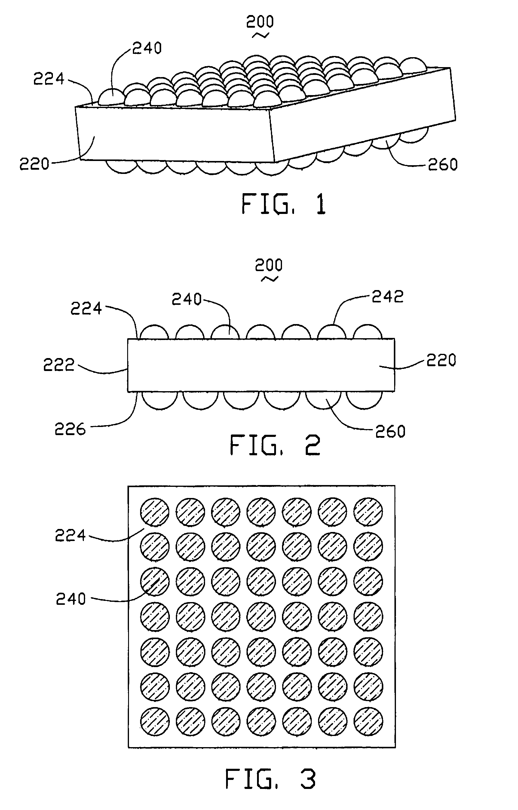
[0022]Referring to FIGS. 1, 2 and 3, a light guide plate 200 in accordance with a preferred embodiment of the present invention includes a transparent plate 220 on which a plurality of identical optical embossments 240 are formed. The transparent plate 220 is generally a flat panel made from polymethyl methacrylate (PMMA). The transparent plate 220 includes an incident surface 222, an emitting surface 224, and a bottom surface 226. The incident surface 222 faces a light source (not shown in the figures), and receives light beams from the light source. The introduced light beams from the incident surface 222 are then directed to and emitted from the emitting surface 224. The incident surface 222 is perpendicular to the bottom surface 226, while the emitting surface 224 is opposite to the bottom surface 226.

[0023]The embossments 240 are evenly distributed on the emitting surface 224, and are integrally formed with the transparent plate 220. The embossments 240 are generally hemispheri...


PUM


Abstract

The present invention provides a light guide plate (500) including a transparent plate (220) having an emitting surface (524) with a plurality of hemispherical embossments (540) formed thereon continuously side-by-side in rows and columns. The transparent plate also has a bottom surface (226) opposite to the emitting surface, with a plurality of hemispherical embossments (260) formed on the bottom surface. The embossments of the emitting and bottom surfaces all face in a direction away from the transparent plate. Other embodiments are also provided.

Description

BACKGROUND OF THE INVENTION[0001]1. Field of the Invention[0002]The present invention relates to a backlight system, and more particularly, to a backlight system having a light guide plate configured for diffusing light beams.[0003]2. Description of the Prior Art[0004]A liquid crystal display is capable of displaying a clear and sharp image through millions of pixels of image elements. It has thus been applied to various equipment in which a message or picture needs to be displayed, such as mobile phones and notebook computers. However, liquid crystal in the liquid crystal display does not itself emit light. Instead, the liquid crystal has to be lit up by a light source so as to clearly and sharply display text, pictures and images.[0005]A conventional backlight system generally comprises a plurality of elements, such as a light source, a reflective plate, a light guide plate, a diffusion plate, and a prism layer. Among these elements, it is generally believed that the light guide p...

Claims


Application Information

Patent Timeline
IPC IPC(8): G02F1/1335F21V7/04F21V8/00G02B6/00
CPCG02B6/0036G02B6/0043
Inventor YU, TAI-CHENGLEU, CHARLESCHEN, GA-LANE
Owner HON HAI PRECISION IND CO LTD
Why Eureka
Try Eureka