Methods and devices for improving the switching times of PLLs

a technology of switching time and switching speed, applied in the direction of phase difference detection of angle demodulation, automatic control of pulses, electrical apparatus, etc., can solve the problems of reducing the time it takes, adversely affecting one another, and improving the switching speed or settling time of plls, so as to reduce the tim

Inactive Publication Date: 2006-07-25
AGERE SYST GUARDIAN +1
View PDF6 Cites 12 Cited by
  • Summary
  • Abstract
  • Description
  • Claims
  • Application Information

AI Technical Summary

Benefits of technology

[0007]In accordance with the present invention, the switching time of a PLL circuit is improved by switching a direct frequency control section into, and out of, the circuit.
[0009]The coarse tuning capability allows the PLL to reduce the time it takes for it to switch from one frequency of operation to another.

Problems solved by technology

Unfortunately, when one characteristic is improved it has adverse affects on another.
For example, improving a PLL's switching speed or settling time has adverse affects on its phase noise and reference spurious suppression.
The time it takes for a PLL to re-tune, however, is limited by its “loop filter bandwidth” (often also optimized for noise and spurious performance) and the maximum current available from a “charge pump” output.

Method used


Image

  • Methods and devices for improving the switching times of PLLs
  • Methods and devices for improving the switching times of PLLs

Examples


Embodiment Construction

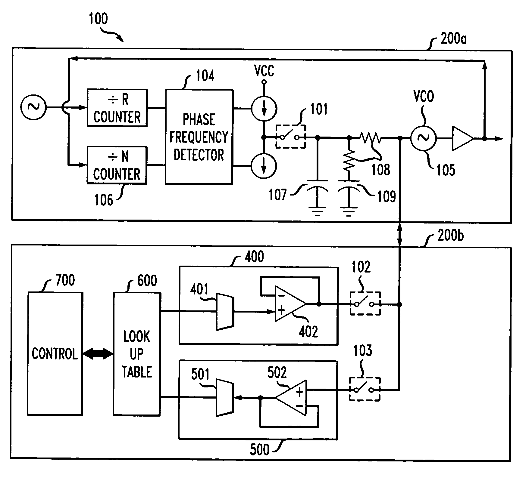
[0012]The present invention provides for a fast switching PLL without sacrificing other important PLL operating characteristics.

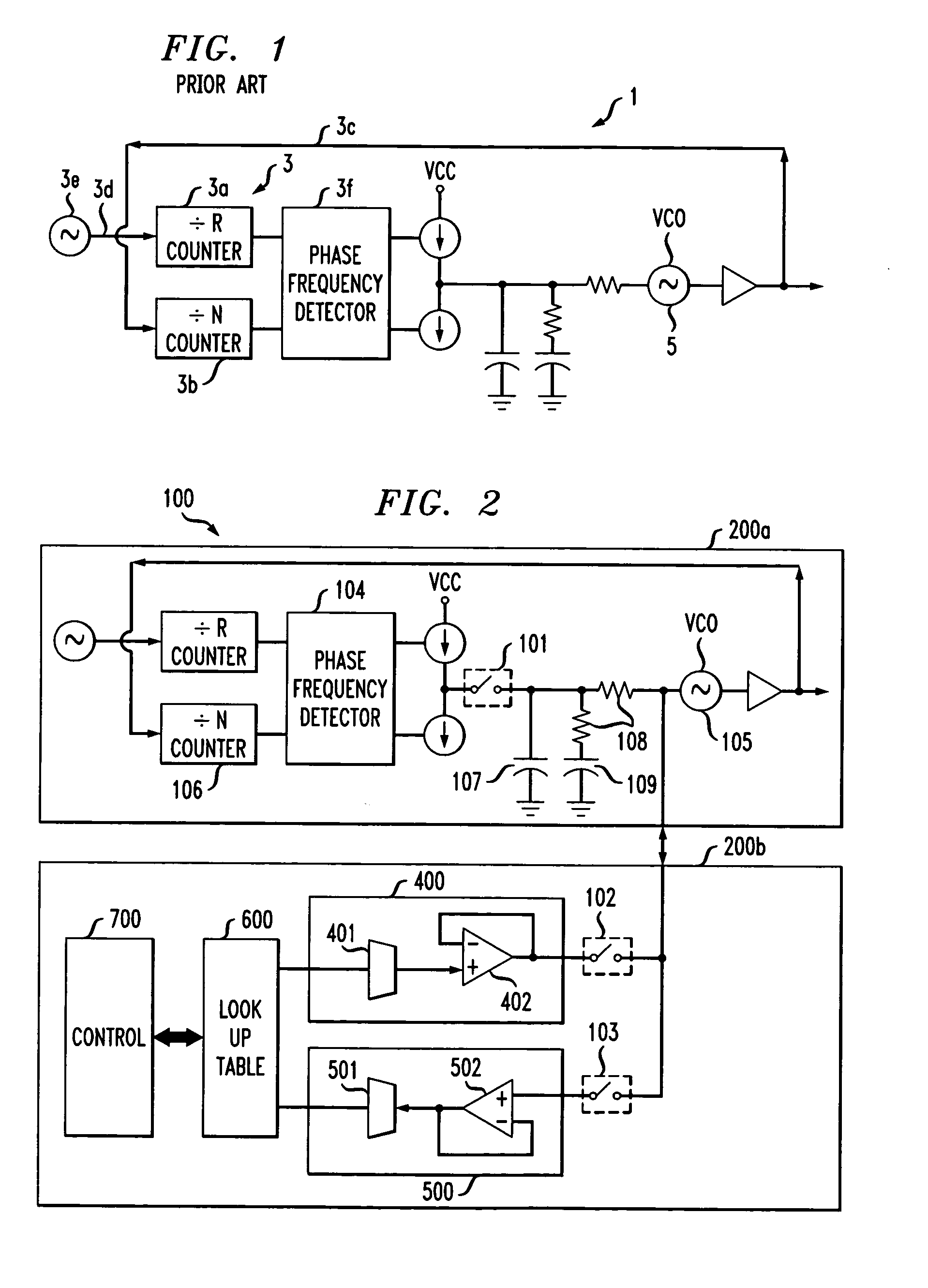
[0013]Referring to FIG. 1, there is shown a conventional PLL 1, the detailed operation of which is known in the art and will not be repeated here. Suffice it to say that many PLLs, including the one shown in FIG. 1, comprise a voltage controlled oscillator (“VCO”) 5. VCOs are used to generate signals which operate over a range of frequencies. The VCO's 5 frequency of operation at any given moment is controlled by a “control voltage”. Typically, the control voltage is generated as follows. First, frequency counters (e.g., dividers and / or multipliers 3a,3b) are adapted to compare two frequencies; one from VCO 5 via pathway 3c and the second from a precise frequency reference 3e via pathway 3d. The two frequencies are compared using a PFD 3f, which in turn generates the control voltage which “closes and locks” a PLL “loop”.

[0014]Referring now to FIG. 2 there i...


PUM


Abstract

The switching time of a phase-locked loop circuit is improved by switching a direct frequency control section, into and out of, the circuit.

Description

BACKGROUND OF THE INVENTION[0001]In the near future new third generation (3G) mobile telephony standards, such as CDMA2000 and W-CDMA (Wideband Code Division Multiple Access) will be introduced. To keep pace, systems and devices need to be re-designed. For example, these new standards will require faster phase-locked loop (hereafter referred to as “PLL”) circuits.[0002]Re-designing a PLL means modifying its operational characteristics. Three common operating characteristics are phase noise, reference frequency spurious suppression and settling time. (i.e., switching speed). Existing attempts to modify PLLs have focused on simultaneously improving all three operating characteristics. Unfortunately, when one characteristic is improved it has adverse affects on another. For example, improving a PLL's switching speed or settling time has adverse affects on its phase noise and reference spurious suppression.[0003]As new, mobile terminals (e.g., wireless telephones, PDAs, etc . . . ) are ...

Claims


Application Information

Patent Timeline
Patent Type & Authority Patents(United States)
IPC IPC(8): H03D3/24H03L7/089H03L7/189
CPCH03L7/189H03L7/0891
Inventor ARKISZEWSKI, ROMAN Z.
Owner AGERE SYST GUARDIAN
Why Eureka
Try Eureka