Gas turbine electric power generation equipment and air humidifier

a technology of electric power generation equipment and gas turbines, which is applied in the direction of hot gas positive displacement engine plants, machines/engines, jet propulsion plants, etc., can solve the problems of large-scale heat exchange equipment, large pressure difference between the inlet and outlet of the gas turbine, and increase in exhaust gas pressure loss, so as to reduce the pressure loss of the working medium

Inactive Publication Date: 2006-08-01
MITSUBISHI HITACHIPOWER SYST LTD
View PDF20 Cites 4 Cited by
  • Summary
  • Abstract
  • Description
  • Claims
  • Application Information

AI Technical Summary

Benefits of technology

[0014]The aforementioned gas turbine electric power generation equipment according to the present invention takes effect of reducing pressure loss of the burned exhaust gas of the gas turbine to improve output or efficiency of electric power generation.
[0038]The aforementioned humidifier according to the present invention takes effect of, while reducing pressure loss of the working medium (particularly, air for burning) of the gas turbine, adding moisture to the working medium for humidification.

Problems solved by technology

, but since the exhaust gas cannot be released into atmosphere at that temperature in terms of environment, exhaust gas from which moisture has been recovered is heat exchanged with exhaust gas prior to recovery of moisture to reheat it.
As a result, heat exchanging equipment becomes large-scaled and pressure loss of exhaust gas increases.
That is, a pressure difference in a working medium between the inlet and outlet of the gas turbine is so small that output of the gas turbine is small.
However, such a point as just mentioned has not been studied in the above-described prior arts.
Therefore, since the conventional humidifying tower is operated in the opposite flow and through the porous medium, pressure loss of compressed air is extremely large.
However, nothing on such a point as described has been studied in the above-described prior arts.

Method used


Image

  • Gas turbine electric power generation equipment and air humidifier
  • Gas turbine electric power generation equipment and air humidifier
  • Gas turbine electric power generation equipment and air humidifier

Examples


first embodiment

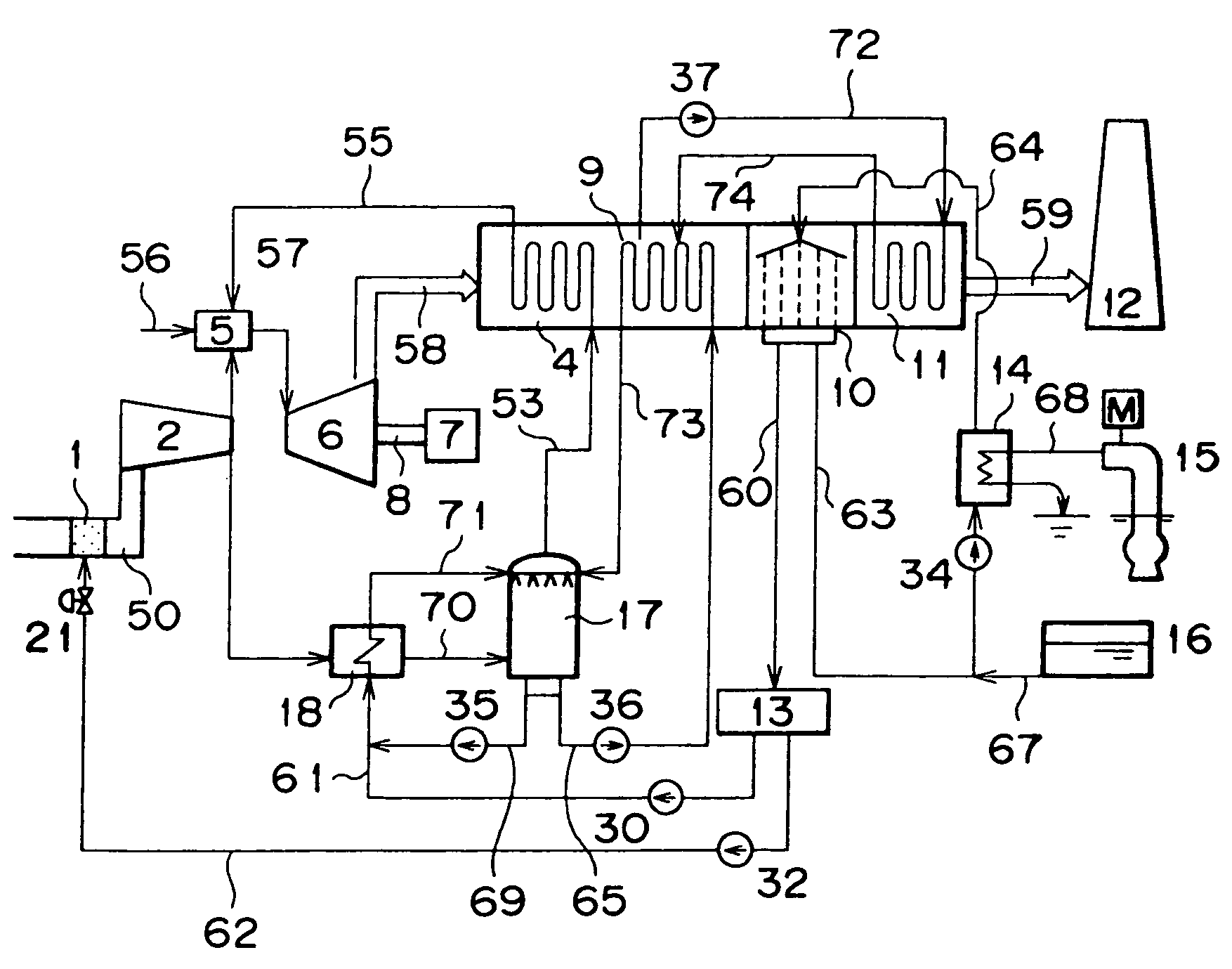
[0047]FIG. 1 shows a system diagram of gas turbine electric power generation equipment according to the present invention. In FIG. 1, reference numeral 1 designates a WAC device for spraying water to air (a); 2 a compressor for compressing the air (a); 3 an air humidifier for humidifying compressed air (b); 4 a regenerator for heating humidified air (c); 5 a combustor for mixing fuel (d) and the humidified air (c) or the compressed air (b) and for burning them to generate combustion gas (e); 6 a turbine driven by the combustion gas (e); 7 a generator for converting power to electricity for generation; 8 a turbine rotor for mechanically connecting the compressor 2, the turbine 6 and the electricity generator 7; 9 a water heater for heating water (k); 10 a water recovery unit for recovering moisture in exhaust gas (f); 11 an exhaust gas reheater for heating the exhaust gas (f); 12 a chimney for releasing the exhaust gas (f); 13 a water processing device for purifying recovery water (g...

second embodiment

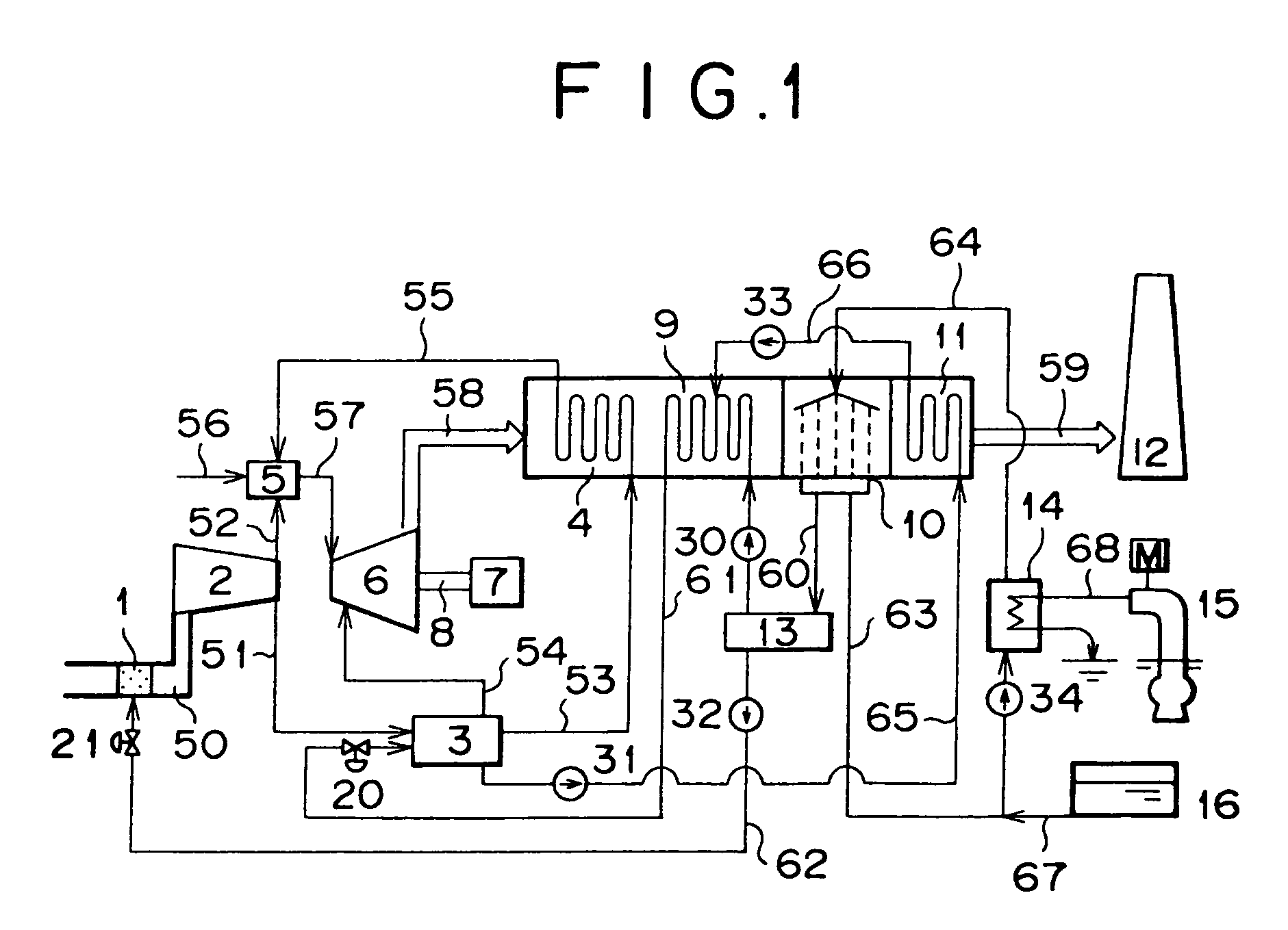
[0084]FIG. 6 is a system diagram of gas turbine electric power generation equipment according to the present invention. In FIG. 6, reference numeral 17 designates an air humidifier for humidifying compressed air (b); 18 a posteriorly disposed cooler for cooling the compressed air (b); 35 to 37 pumps for boosting liquid; 69 a surplus water line through which surplus water (h) flows; 70 a compressed air line through which the compressed air (b) cooled in the posteriorly disposed cooler 18 flows; and 71 to 74 water lines through which water (k) flows.

[0085]A difference from the gas turbine electric power generation equipment shown in FIG. 1 is that as the air humidifier 17, there is used a well-known humidifying tower in which compressed air and waterdrops are brought into contact in opposite flow and directly, and that in the exhaust gas reheater 11, exhaust gas (f) is heated using a part of the water (k).

[0086]That is, the compressed air (b) is supplied to the posteriorly disposed co...

third embodiment

[0094]FIG. 7 is a system diagram of gas turbine electric power generation equipment according to the present invention. In FIG. 7, reference numeral 22 designates an adjusting valve for adjusting flow rate, and 75 and 76 blade cooling water lines through which blade cooling water (p) flows.

[0095]A difference from the gas turbine electric power generation equipment shown in FIG. 1 is that a part of surplus water (h) cooled in the exhaust gas reheater 11 is used to cool the turbine 6.

[0096]That is, a part of surplus water (h) cooled in the exhaust gas reheater 11 is supplied, as the blade cooling water (p), to the turbine 6 via the blade cooling water line 75. In the turbine 6, the blade cooling water (p) is circulated in a turbine static blade or the like to cool the turbine static blade or the like. The turbine static blade or the like is cooled whereby the blade cooling water (p) heated in the turbine 6 is merged with the water (k) having passed through the water line 61 via the bl...


PUM


Abstract

The present invention relates to an air humidifier for adding moisture to a working medium of a gas turbine for humidification, and gas turbine electric power generation equipment for driving the gas turbine by the working medium of high moisture to general electricity. An object of the present invention is to reduce pressure loss of burned exhaust gas of the gas turbine to improve output or efficiency of electric power generation. There comprises a humidifier (3), a combustor (5), a turbine (6), a generator (7), and a water recovery unit (10), further comprises an exhaust gas reheater (11) for heating burned exhaust gas discharged from the water recovery unit by surplus water discharged from the humidifier.

Description

[0001]This is a continuation application of U.S. Ser. No. 11 / 058,366, filed Feb. 16, 2005, which is a divisional of U.S. Ser. No. 10 / 673,164, filed Sep. 30, 2003, now U.S. Pat. No. 6,901,736; which is a divisional of U.S. Ser. No. 09 / 463,231, filed Jan. 21, 2000, now U.S. Pat. No. 6,644,013. This application is related to the U.S. Ser. No. 10 / 301,609, filed Nov. 22, 2002, now U.S. Pat. No. 6,578,354.TECHNICAL FIELD[0002]The present invention relates to an air humidifier for adding moisture to a working medium of a gas turbine for humidification, and gas turbine electric power generation equipment in which a gas turbine is driven by the working medium of high moisture, and moisture is recovered from gas turbine exhaust gases for recycle or recirculation, and particularly to an air humidifier and gas turbine electric power generation equipment which reduce pressure loss of the working medium or pressure loss of the gas turbine exhaust gas.BACKGROUND ART[0003]As a prior art relating to...

Claims


Application Information

Patent Timeline
Patent Type & Authority Patents(United States)
IPC IPC(8): F02C3/30
CPCF02C3/30F02C3/305F02C7/1435F02C6/18Y02E20/16Y02E20/14
Inventor HATAMIYA, SHIGEOYAMAGISHI, MASAHIKOYOKOMIZO, OSAMU
Owner MITSUBISHI HITACHIPOWER SYST LTD
Why Eureka
Try Eureka