Compact co-axial rotor system for a rotary wing aircraft and a control system thereof

a rotary wing aircraft and coaxial rotor technology, applied in the direction of rotors, marine propulsion, vessel construction, etc., can solve the problems of reducing the separation of tips, reducing the size of the conventional helicopter configuration, and requiring a relatively large separation between the rotor systems, so as to reduce the separation of blades and reduce the flapping of blades and the effect of blade elastic bending

Active Publication Date: 2006-08-01
SIKORSKY AIRCRAFT CORP
View PDF10 Cites 57 Cited by
  • Summary
  • Abstract
  • Description
  • Claims
  • Application Information

AI Technical Summary

Benefits of technology

[0006]The invention described herein utilizes rotor position control through a variety of methods singularly, or in any combination determined to be most advantageous, to reduce the separation between coaxial rotors and hence reduce the overall height of the aircraft such that the aircraft fits within the hangar deck of an amphibious assault ship.
[0009]The present invention determines the relative position of the blades of each rotor system and independently controls each rotor and or blade such that blade flapping and blade elastic bending are significantly reduced, hence enabling reduced rotor separation.

Problems solved by technology

Thus, a conventional helicopter configuration like the CH-53E would be too large to fit in the hangar deck or on the elevator of an LHA or LHD.
Disadvantageously, conventional dual counter rotating coaxial rotor systems require a relatively large separation between the rotor systems.
Since the rotors are counter rotating, many maneuvers cause mirror image, or differential, rotor tilt, which reduces tips separation at some point in the rotation.
Disadvantageously, application of such rotor spacing to a heavy lift VTOL aircraft which are capable of emerging vertical lift requirements result in an aircraft which will likely not meet current shipboard height compatibility restrictions.

Method used


Image

  • Compact co-axial rotor system for a rotary wing aircraft and a control system thereof
  • Compact co-axial rotor system for a rotary wing aircraft and a control system thereof
  • Compact co-axial rotor system for a rotary wing aircraft and a control system thereof

Examples


Embodiment Construction

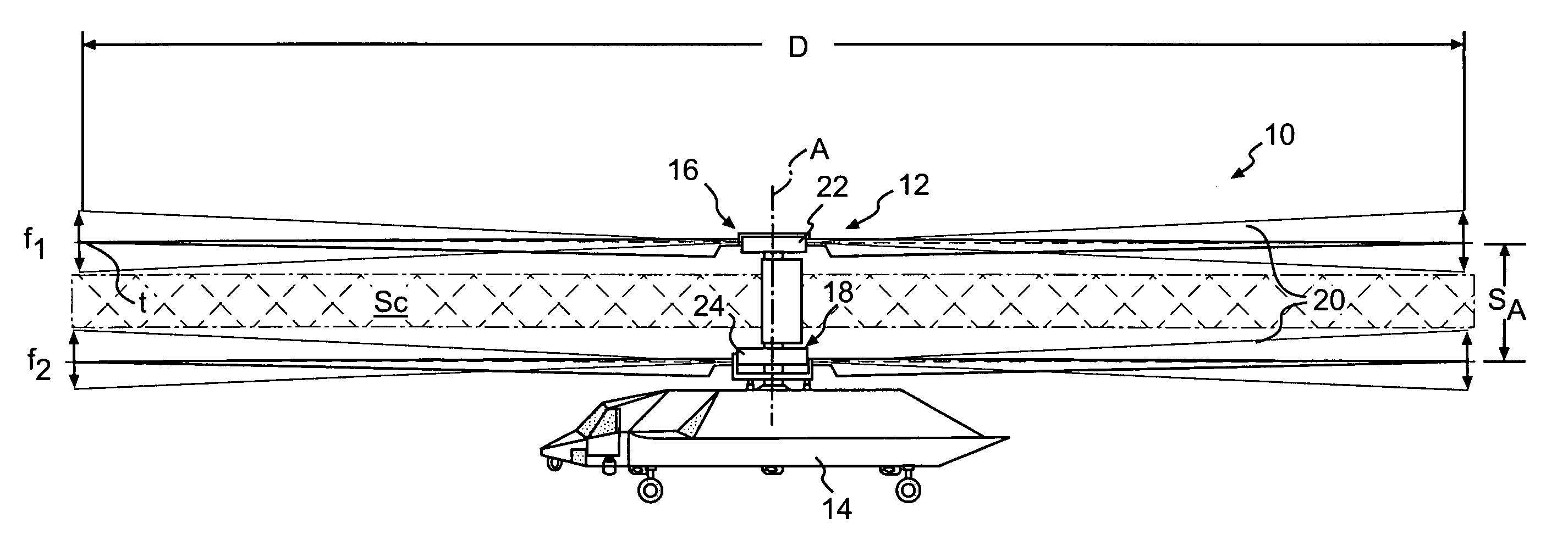
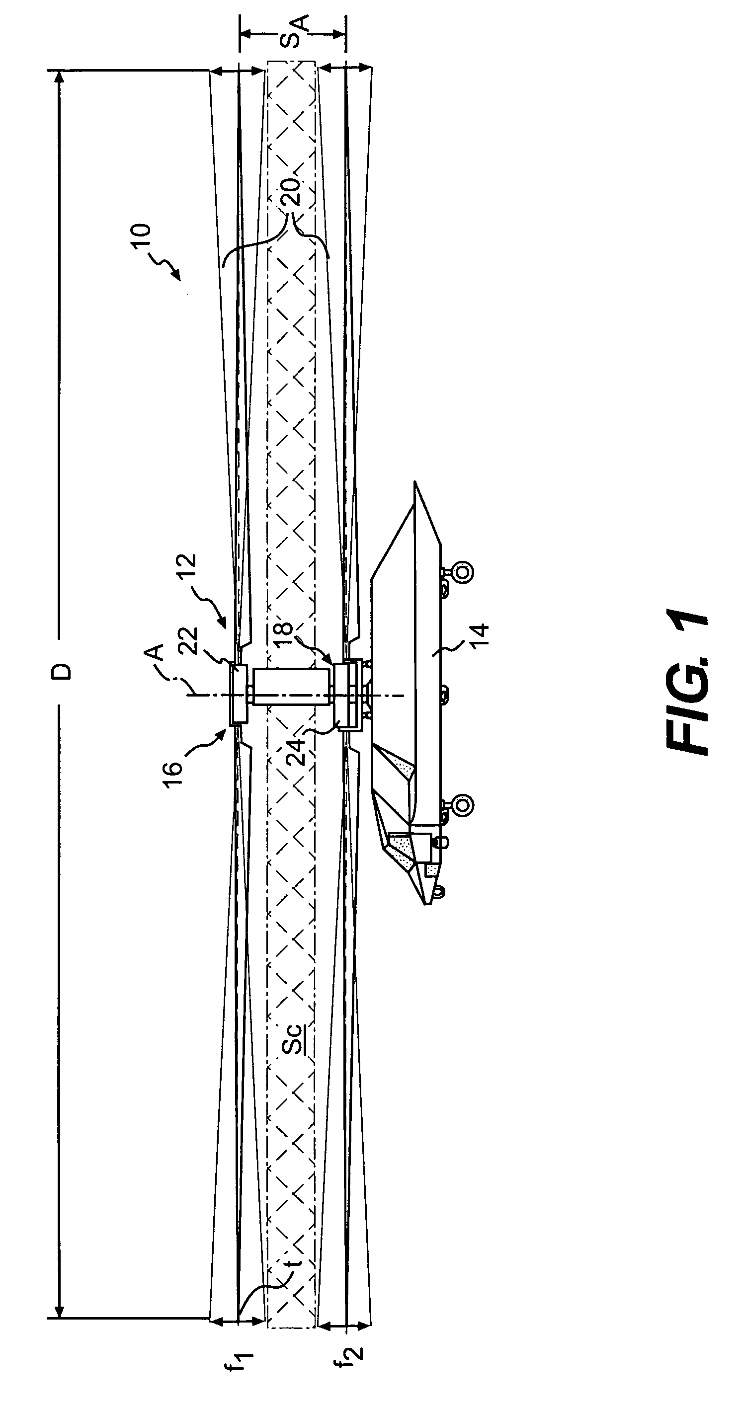
[0022]FIG. 1 schematically illustrates a rotary-wing aircraft 10 having a dual, counter rotating, coaxial rotor system 12. The aircraft 10 includes an airframe 14 which supports the dual, counter rotating, coaxial rotor system 12 along a common axis A. Although a particular helicopter configuration is illustrated in the disclosed embodiment, other coaxial propulsor systems which require closely spaced rotors or propellers in helicopter, airplane and / or tilt rotor type aircraft will also benefit from the present invention.

[0023]The rotor system 12 includes an upper rotor system 16 and a lower rotor system 18 which rotate about the common axis A. Each rotor system 16, 18 include a multiple of rotor blades 20 mounted to a rotor hub 22, 24.

[0024]The rotor systems 16, 18 are separated by an axial rotor separation distance Sa of less than 10 percent of the rotor system diameter D along common axis A. Preferably, the rotor systems 16, 18 are separated by an axial distance of approximately ...


PUM


Abstract

A dual, counter rotating, coaxial rotor system provides an upper and lower rotor system, with a reduced axial rotor separation distance along a common axis by way of rotor tip position sensing and rotor position controls to avoid tip contact.

Description

BACKGROUND OF THE INVENTION[0001]The present invention relates to a coaxial rotor system, and more particularly to a coaxial rotor system with closely spaced articulated rotors.[0002]Future military forces require enhanced vertical lift capabilities in a compact package. The CH-53E is currently the world's largest shipboard compatible helicopter. A significant consideration in the design of the CH-53E was shipboard compatibility. The CH-53E effectively defines the maximum aircraft spatial capacity which will fit on the elevators and in the hangar deck of United States Marine Corps Amphibious Assault Ships, more commonly called an LHA or LHD. Emerging payload weight requirements are beyond the growth capabilities of the CH-53E while maintaining current shipboard compatibility requirements. Thus, a conventional helicopter configuration like the CH-53E would be too large to fit in the hangar deck or on the elevator of an LHA or LHD.[0003]Conventional coaxial rotor systems are exceeding...

Claims


Application Information

Patent Timeline
Patent Type & Authority Patents(United States)
IPC IPC(8): B64C11/34B64C27/08B64C27/10B64C27/32B64C27/46B64C27/605B64C27/615
CPCB64C27/10B64C27/322B64C27/605B64C27/615B64C27/46Y02T50/34Y02T50/30
Inventor SCOTT, MARK WINFIELD
Owner SIKORSKY AIRCRAFT CORP
Why Eureka
Try Eureka