Pattern-definition device for maskless particle-beam exposure apparatus

a technology of maskless particle beams and pattern definition devices, which is applied in the field of pattern definition devices and exposure apparatuses, can solve the problems of residual aberrations, blockage of beamlet passage, and inability to precisely telecentric illumination beams, and achieve the effect of minimizing the aberration of crossover

Active Publication Date: 2006-08-01
HEWLETT PACKARD DEV CO LP +1
View PDF7 Cites 84 Cited by
  • Summary
  • Abstract
  • Description
  • Claims
  • Application Information

AI Technical Summary

Benefits of technology

[0021]Of course, these aspects may be combined with each other. In particular, an advantageous combination may result in a PD device comprising two deflector array means. In this variant the first deflector array means is adapted to adjust the angles of the beamlets passing the apertures to minimize the aberration of a crossover formed in a projection optics after said device in the particle-beam exposure apparatus, and the second deflector array means is adapted to produce a virtual object different from the object as defined by the apertures of the aperture array means; additionally, the two deflector array means are able to adjust the position of the virtual object and the angles of the beamlets independently from each other.

Problems solved by technology

With the above PD layouts, the general problem arises that the illuminating beam is actually not exactly telecentric (or homocentric, as the case may be), but has residual aberrations, due to unavoidable higher orders of the lenses and / or individual deficiencies of the lens elements.
This may cause a situation where the passage of a beamlet is blocked since the local direction of the beamlet is not in line with the arrangement of consecutive openings in the plate components of the PD device.
Such an arrangement is not possible in a PD device of the kind described above, due to the restricted space between the apertures and due to the high number of apertures—individual control of each fine-deflection unit would be unmanageable.

Method used


Image

  • Pattern-definition device for maskless particle-beam exposure apparatus
  • Pattern-definition device for maskless particle-beam exposure apparatus
  • Pattern-definition device for maskless particle-beam exposure apparatus

Examples


Embodiment Construction

[0043]The preferred embodiment discussed in the following is based on the pattern definition (PD) system disclosed in the U.S.-2003-0155534-A1. In the following, the technical background of the PD system, as far as relevant to the invention, is first discussed with reference to FIGS. 1 to 5 (which were taken, with modifications where appropriate, from the U.S.-2003-0155534-A1), then an embodiment of the invention in the PD system is illustrated in FIGS. 6 to 15. It should be appreciated that the invention is not restricted to the embodiment discussed in the following, which merely represents one of the possible implementations of the invention.

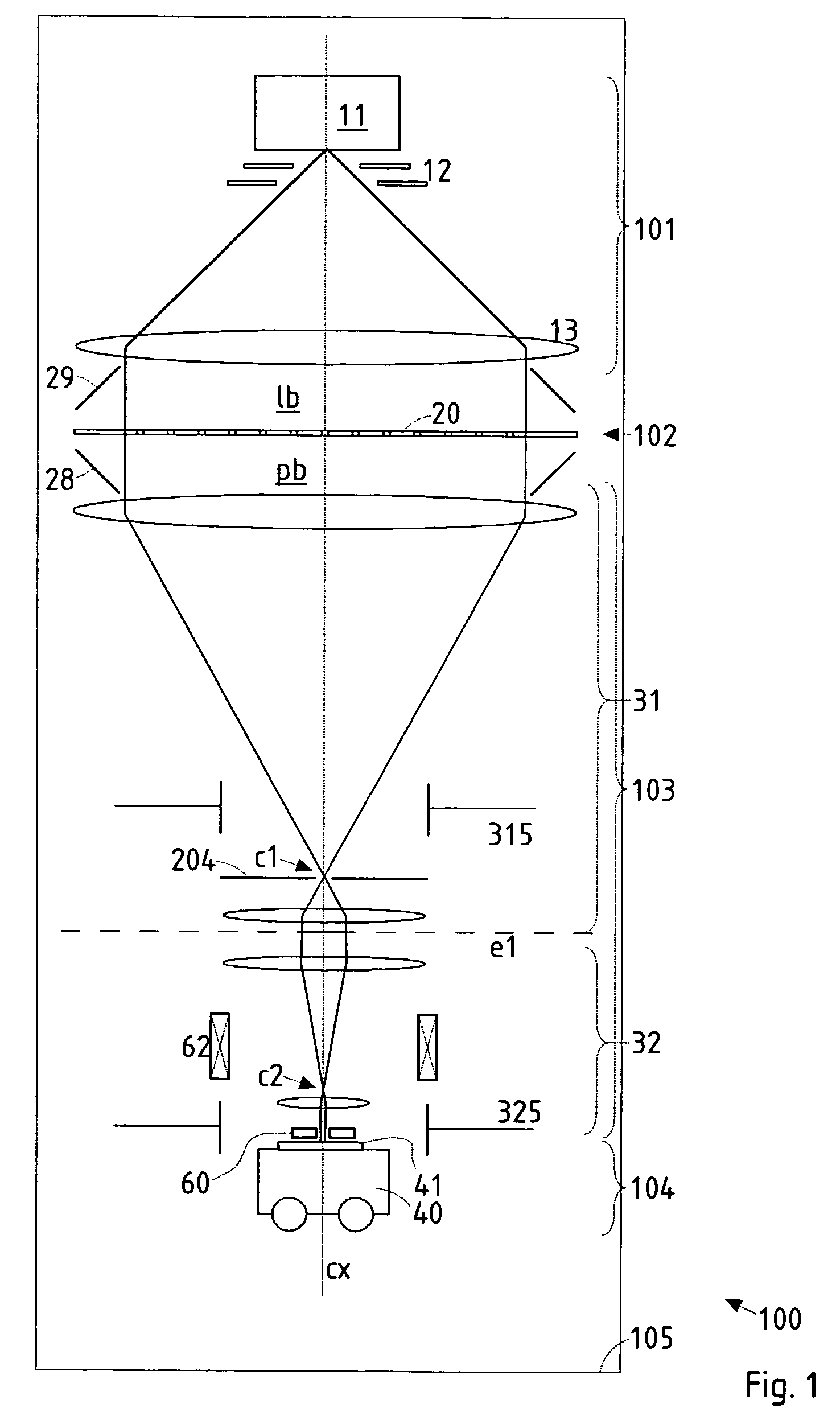
[0044]An overview of a lithographic apparatus employing the preferred embodiment of the invention is shown in FIG. 1. In the following, only those details are given as needed to disclose the invention; for the sake of clarity, the components are not shown to size in FIG. 1. The main components of the lithography apparatus 100 are—corresponding...


PUM


Abstract

In a pattern-definition device (102) for use in a particle-beam exposure apparatus, a beam of electrically charged particles is patterned through a plurality of apertures. The device comprises at least one deflector array means having a plurality of openings surrounding the beamlets, wherein for each opening are provided at least two deflecting electrodes to which different electrostatic potentials are appliable, thus correcting the path of the beamlet(s) passing through the respective opening according to a desired path through the device (102). According to a partition of the plurality of apertures into a set of subfields (Aij), the deflecting electrodes belonging to the same subfield (Aij) have common electric supplies. Thus, the electrostatic potentials of the deflecting electrodes belonging to the same subfield (Aij) are constant or linearly interpolated between basic potentials fed at basic points (Pij) of the respective subfield.

Description

CROSS-REFERENCE TO RELATED APPLICATIONS[0001]This application claims the benefit of Austrian Patent Application Serial No. A 1711 / 2003, filed 28 Oct. 2003.FIELD OF THE INVENTION AND DESCRIPTION OF PRIOR ART[0002]The invention relates to a pattern definition device and an exposure apparatus employing this pattern definition means. The pattern definition device is used in a maskless particle-beam exposure apparatus for forming a pattern on a surface of a substrate by means of a beam of energetic electrically charged particles. More in detail, the pattern definition device is a means for defining a pattern in a particle-beam exposure apparatus, which device is adapted to be irradiated with a beam of electrically charged particles and allow the passage of the beam only through a plurality of apertures. It comprises an aperture array means which has a plurality of apertures defining the shape of beamlets permeating said apertures, as well as at least one deflector array means separate fr...

Claims


Application Information

Patent Timeline
Patent Type & Authority Patents(United States)
IPC IPC(8): H01J37/08H01J37/305H01J37/147H01J37/317H01L21/027
CPCB82Y10/00B82Y40/00H01J37/15H01J37/3177H01J37/3174H01J2237/31776H01J2237/0453H01J2237/31774H01J37/04H01J37/1471H01J37/3172
Inventor LAMMER-PACHLINGER, WOLFGANGLAMMER, GERTRAUDCHALUPKA, ALFRED
Owner HEWLETT PACKARD DEV CO LP
Why Eureka
Try Eureka