Small-sized piezoelectric resonator

a piezoelectric resonator, small technology, applied in piezoelectric/electrostrictive devices, impedence networks, electrical apparatus, etc., can solve the problem that the ratio between the length and the width of the resonator is not very good for the manufacture of such cases, the connection of the resonator and the case to the case is liable to tip towards the bottom of the case, and the resonator and the connection to the case do not have very good shock shock shock

Active Publication Date: 2006-08-01
ETA SA MFG HORLOGERE SUISSE
View PDF10 Cites 55 Cited by
  • Summary
  • Abstract
  • Description
  • Claims
  • Application Information

AI Technical Summary

Benefits of technology

[0010]The main goal of the invention is to provide a three arm resonator which enables to reduce consumption of energy by producing an excitation electrical field which is more homogeneous and locally more intense and for which vibration loss at the arms is low even when the size of the vibrating piece is miniaturized and the Cl value (crystal impedance or equivalent series resistance) can also be suppressed at a low level.
[0011]For that purpose according to a first aspect of the invention, it concerns a piezoelectric resonator including a tuning fork shaped part with two parallel vibrating arms, connected to each other by a linking part, from which protrude a central arm located between both vibrating arms of the tuning fork shaped part, wherein at least one groove is formed on at least one of a front side and a rear side of each vibrating arm. Use of grooves on the vibrating arms furnishes precise performances even when the device is miniaturized.

Problems solved by technology

One of these problems is that the dimensional and functional features of the conventional tuning fork resonators are optimised for mounting them in metallic cases and not in ceramic cases.
For example, the ratio between their length and their width is ill suited to the manufacture of such cases, in particular when the cases are of the SMD (Surface Mounting Device) type, i.e. meant to be automatically mounted on hole-free printed circuit boards.
Because of this, a conventional tuning fork resonator and its connection to the case do not have very good resistance to shocks.
Further conventional tuning fork resonators are liable to tip towards the bottom of the case when it is fixed onto a step of the case.
Furthermore, since the thermal expansion coefficients of ceramic material and quartz are different enough to create mechanical stresses in the resonator which can not only be felt in the arms of the tuning fork and disturb the working of the resonator when the temperature changes but can also break the solder or detach connection pads of the resonator from those of the case and alter or even cut the electric connection between the resonator electrodes and the external contact pads of the case.
For the same reason, if there is an incipient fracture on the side of base of the tuning fork where connection pads are situated, a significant temperature variation can even break the tuning fork.
Nevertheless although these three arm resonators have proved to be advantageous, miniaturization requirements as well as energy consumption required to maintain vibrations of the tuning fork are always critical issues for mobile phone or wristwatch applications.

Method used


Image

  • Small-sized piezoelectric resonator
  • Small-sized piezoelectric resonator
  • Small-sized piezoelectric resonator

Examples


first embodiment

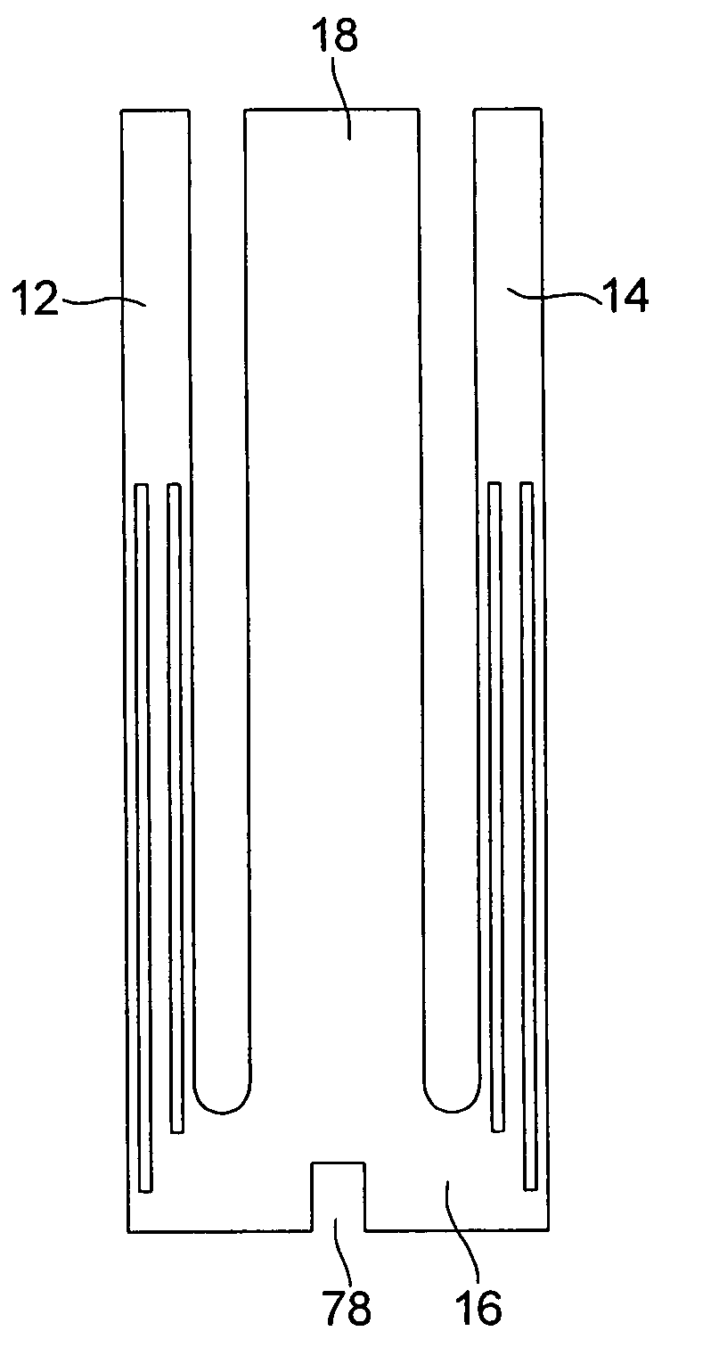
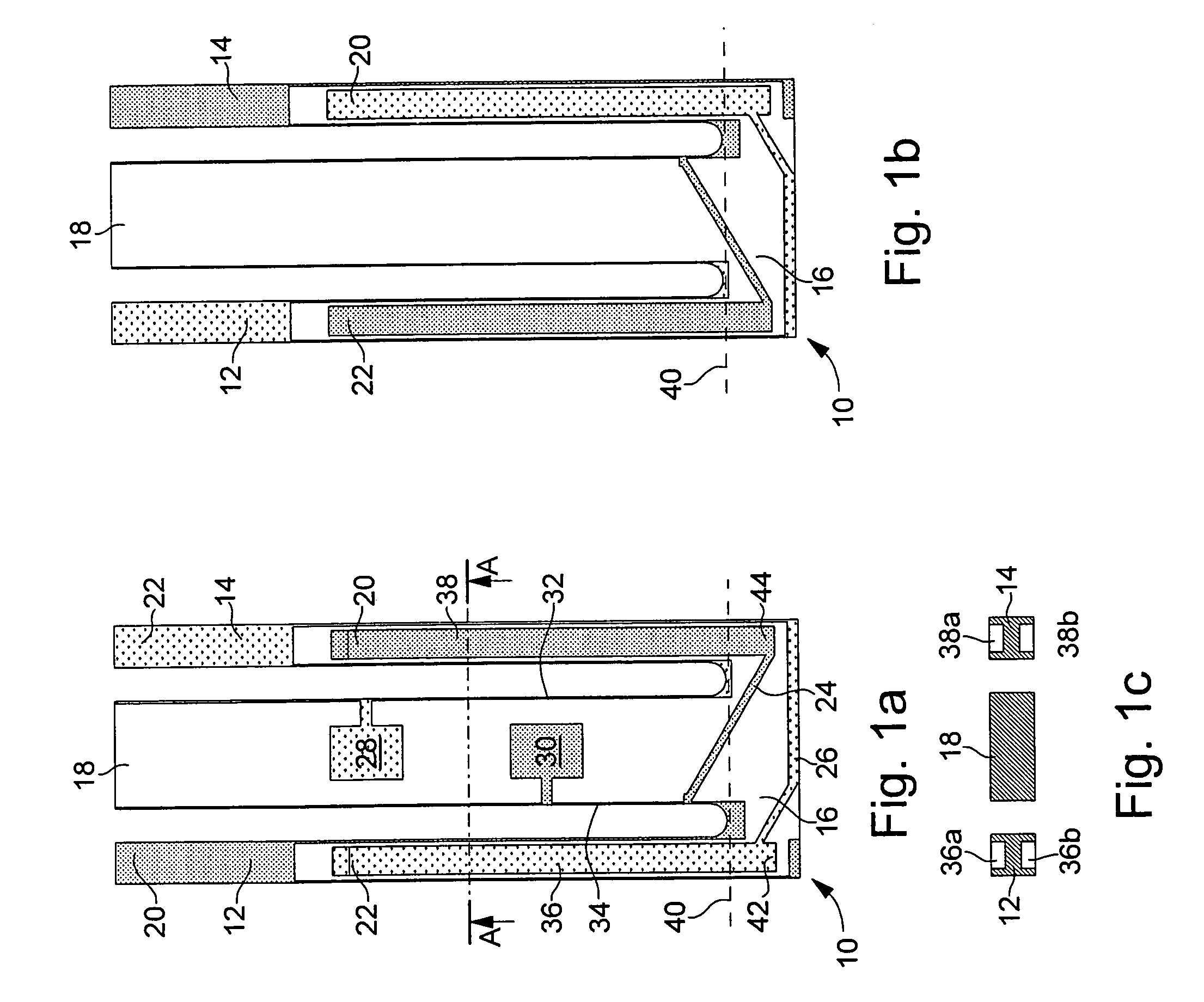
[0037]In the first embodiment shown in relation with FIGS. 1a, 1b and 1c, the resonator according to the invention, designated by the reference numeral 10, includes a tuning fork shaped part with two vibrating arms 12 and 14 joined by a linking part 16 to which a central arm 18, located between arms 12 and 14 and parallel thereto, is attached, the whole assembly being made in a single piece and of quartz.

[0038]As shown by FIGS. 1a and 1b, vibrating arms 12 and 14 carry two groups of electrodes 20 and 22, which are connected to each other by conductive paths respectively 24 and 26, carried by linking part 16 of the tuning fork shaped part. As they are shown in the drawing, these electrodes and conductive paths are disposed to make arms 12 and 14 vibrate in flexure mode, but they could have a different configuration to make the arms vibrate in the same mode or another mode (torsion, shear, etc.). Returning to central arm 18, FIG. 1a shows that it carries on its back face two conductiv...

second embodiment

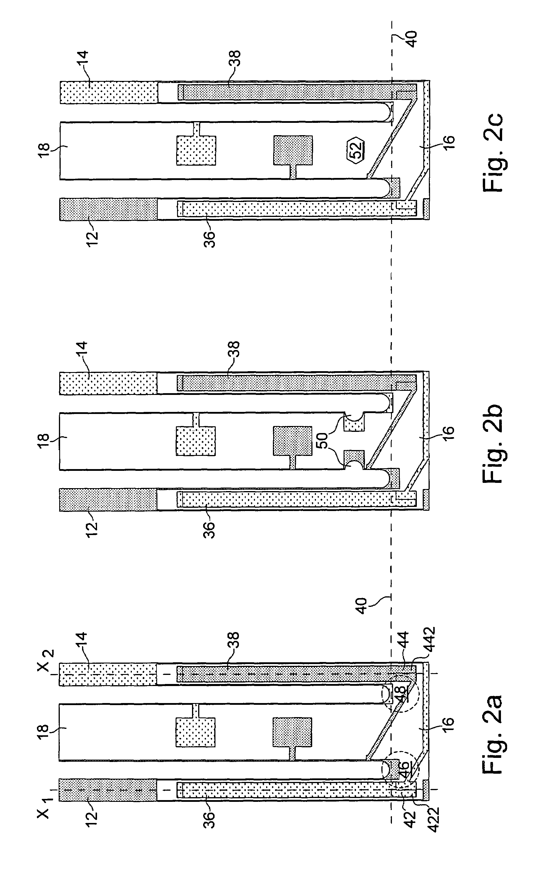
[0047]One retrieves as for the second embodiment, two variants with decoupling means being located between fixing elements 28 and 30 and linking part 16 to which vibrating arms 12 and 14 are attached. These decoupling means are respectively notches 50 in FIG. 3b and a hole 52 in FIG. 3c. Once again, it will be appreciated that both variants of FIGS. 3b and 3c may be combined.

fourth embodiment

[0048]In the fourth embodiment shown in FIG. 4, the resonator differs from the one shown in FIG. 3a in that in order to guarantee a better mechanical resistance of the resonator in the high stressed areas, exterior grooves 364, respectively 382 which are located on the inside with respect to central arm 18 extend shorter within linking part 16 than interior grooves 362, respectively 384 which are located on the outside with respect to central arm 18. Thus, the quantity of material in the high mechanical stressed areas, which are illustrated by hatched zones 46 and 48 and mainly located in the linking part regions contiguous to vibrating arms 12 and 14, is more important and therefore renders these areas more robust to mechanical constraints.

[0049]In the two variants of the fifth embodiment respectively shown in FIGS. 5a and 5b, the resonator differs from the one shown in relation with FIG. 4 in that fixing and positioning means are arranged on central arm 18. According to this fifth...


PUM


Abstract

The piezoelectric resonator according to the invention includes a tuning fork shaped part with two parallel vibrating arms, connected to each other by a linking part, from which protrude a central arm located between both vibrating arms of the tuning fork shaped part, wherein at least one groove is formed on at least one of a front side and a rear side of each vibrating arm.

Description

FIELD OF INVENTION[0001]The present invention concerns piezoelectric resonators and more particularly resonators of small dimensions which are most often used for making frequency generators in particular for portable electronic equipment, in numerous fields such as horology, information technology, telecommunications and the medical field.BACKGROUND OF THE INVENTION[0002]Such a resonator of small dimensions has been disclosed in the prior art document U.S. Pat. No. 6,700,313 filed in the name of the name Assignee, which is enclosed herewith by way of reference. Resonator 10 represented on FIG. 13, which is intended to be mounted in a case, includes a tuning fork shaped part with two parallel arms 12, 14 connected to each other by a linking part 16 and carrying electrodes 20, 22 to make them vibrate, these electrodes being connected to connecting pads 28, 30 intended to be electrically connected to the exterior of the case. Resonator 10 also includes a central arm 18 attached to lin...

Claims


Application Information

Patent Timeline
Patent Type & Authority Patents(United States)
IPC IPC(8): H01L41/08
CPCH03H9/21
Inventor DALLA PIAZZA, SILVIOSTUDER, BRUNOLUETHI, THOMAS
Owner ETA SA MFG HORLOGERE SUISSE
Why Eureka
Try Eureka