Optical disc drive having OPC control unit for controlling the level of power of the laser beam for recording and reading data from an optical disc

a technology of optical discs and control units, applied in the field of optical disc drives, can solve the problems of jitter or high error rate of reproduced signals, degraded produced signals, and inability to accurately compensate recording power, etc., to achieve the effect of improving the accuracy of measuring the strength value of reflected signals

Inactive Publication Date: 2006-08-01
TEAC CORP
View PDF4 Cites 14 Cited by
  • Summary
  • Abstract
  • Description
  • Claims
  • Application Information

AI Technical Summary

Benefits of technology

[0032]According to the present invention, it is possible to enhance the accuracy of measuring the strength value of the reflected light during the OPC operation and the running OPC operation.

Problems solved by technology

When the data are recorded on the CD-R disc by means of the laser beam that does not have the optimum power for the CD-R disc, a jitter and an error rate of a reproduced signal might cause the reproduced signal to be degraded.
Therefore, it causes the problem that the jitter or the error rate of the reproduced signal becomes high until the recording power is controlled to the actual optimum recording power.
As a result, the recording power cannot be compensated accurately if the running OPC is performed based on the strength of the reflected light from the pit during the OPC, because the error is included in the measurement value of the strength of the reflected light from the pit during the OPC.
As a result, both the error rate and the jitter of the reproduced signal become high because it is impossible to keep the value β of the reproduced signal at the value β determined during OPC if the running OPC cannot keep the recording power at the optimum recording power.

Method used


Image

  • Optical disc drive having OPC control unit for controlling the level of power of the laser beam for recording and reading data from an optical disc
  • Optical disc drive having OPC control unit for controlling the level of power of the laser beam for recording and reading data from an optical disc
  • Optical disc drive having OPC control unit for controlling the level of power of the laser beam for recording and reading data from an optical disc

Examples


Embodiment Construction

[0039]A first embodiment according to the present invention will be explained.

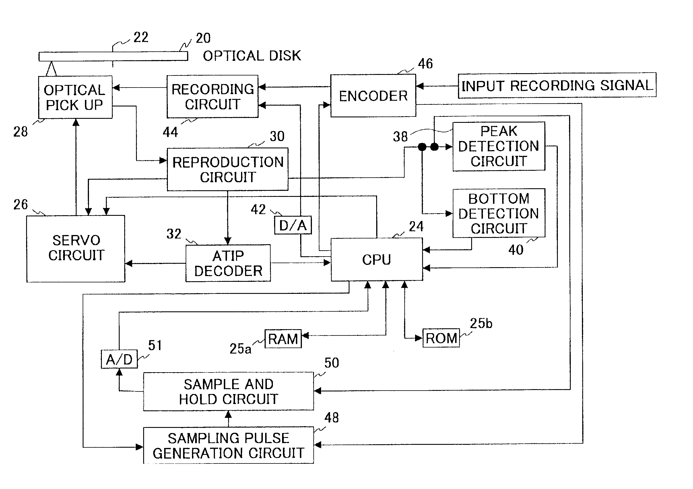
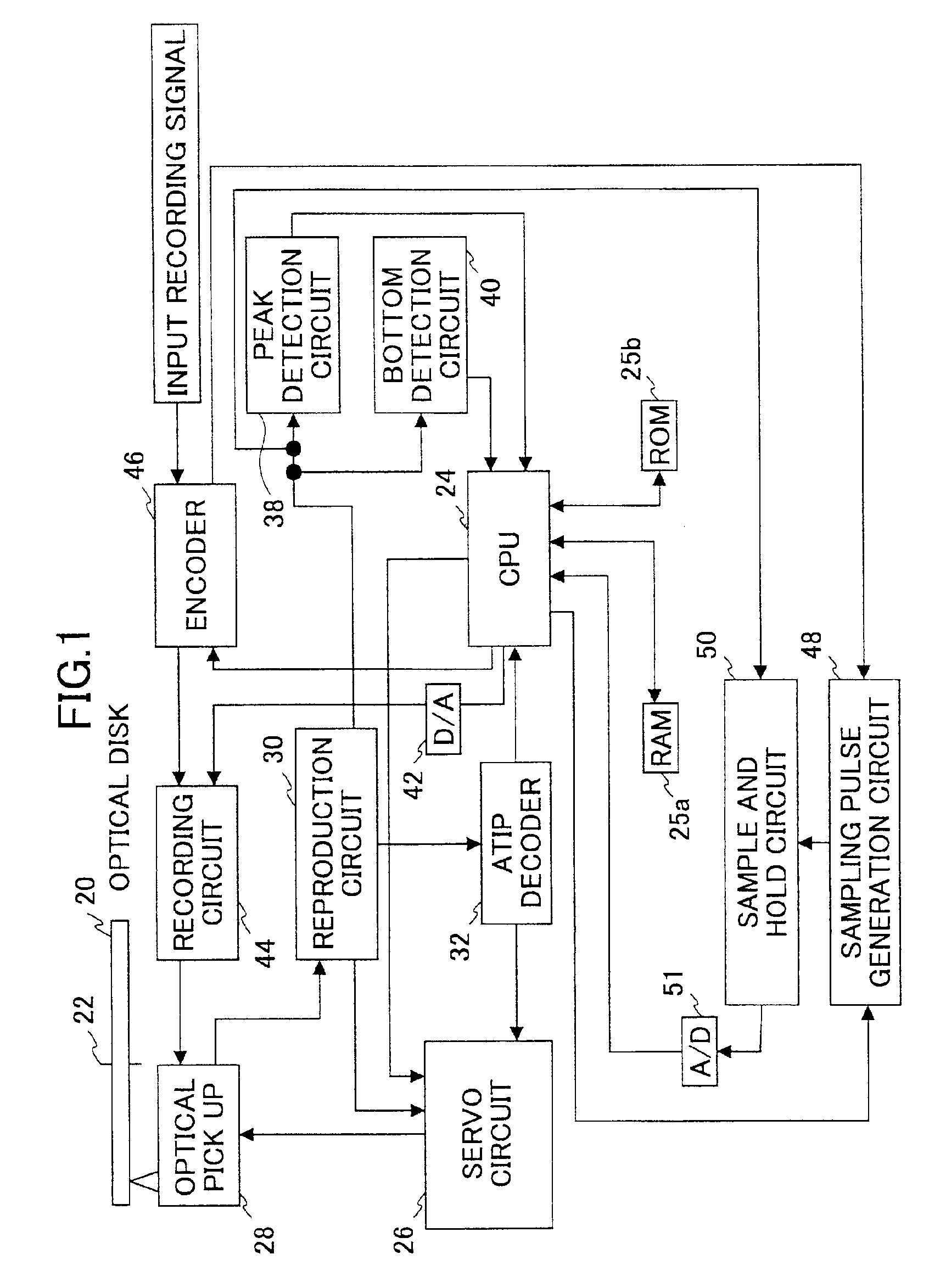
[0040]FIG. 1 shows a block diagram of an optical disc drive of an embodiment according to the present invention. In FIG. 1, an optical disc 20 is rotated by the spindle motor around a mandrel 22. A micro processor (CPU) 24 provides commands to a servo circuit 26 based on write / read commands provided by the upper apparatus described later.

[0041]The servo circuit 26 performs a CLV (constant linear velocity) servo operation to control the spindle motor. The servo circuit 26 also controls a sled motor to move an optical pick-up 28 to a desired block on the optical disc 20 and also executes a focusing servo control operation and a tracking servo control operation to the optical pick-up 28.

[0042]A laser beam radiated from the optical pick-up 28 is reflected from a recording layer of the optical disc 20 and the reflected laser beam is detected by the optical pick-up 28. The optical pick-up 28 generates a reproduc...


PUM

PropertyMeasurementUnit
frequencyaaaaaaaaaa
frequencyaaaaaaaaaa
strengthaaaaaaaaaa

Abstract

An optical disc drive has an OPC control unit that records the signal to a plurality of frames in the predetermined test area on the optical disc using a plurality of recording power values and repeatedly records the signal to another plurality of frames in the predetermined test area on the optical disc using the plurality of recording power values, and calculates an average strength value of the reflected light of the plurality of strength values of the reflected lights from the plurality of frames in which frames the signal is recorded with the same recording power value, and the average strength value of the reflected light corresponding to the optimum recording power value is determined as an optimum strength value of the reflected light , during the OPC operation, and a recording power control unit that modifies the recording power value by a predetermined value in order to make the strength value of the reflected light from the pit portion during recording move toward the optimum strength value of the reflected light, during the running OPC operation. As a result, the present invention provides the optical disc drive, in which data can be recorded with an optimum recording power over the whole disc and both a jitter and an error rate of the reproduced signal are kept low.

Description

BACKGROUND OF THE INVENTION[0001]1. Field of the Invention[0002]The present invention generally relates to an optical disc drive, and more particularly to an optical disc drive which records data on the optical disc and reads the data from the optical disc.[0003]2. Description of the Related Art[0004]There are two types of recordable type optical discs, such as a write-once type and an erasable type. There are several methods to record data on the write-once type optical disc. In one method, Te or Bi is used for the material of a recording layer of the write-once type optical disc and pits are formed on the recording layer by means of melting the material by means of radiating a laser beam to the material. In another method, a thin film composed of a material such as Sb2Se3, TeOx or an organic dye is used for a recording layer of the write-once type optical disc and reflectance of the recording layer is changed by means of radiating a laser beam to the material.[0005]A CD-R disc, wh...

Claims


Application Information

Patent Timeline
Patent Type & Authority Patents(United States)
IPC IPC(8): G11B5/09G11B7/004G11B7/0045G11B7/125G11B7/126G11B7/1263G11B7/1267
CPCG11B7/1263G11B7/1267G11B7/126G11B7/00454G11B7/00455G11B7/0045G11B7/004
Inventor OGAWA, TOSHIHIRO
Owner TEAC CORP
Why Eureka
Try Eureka