Underground electrical cable with temperature sensing means

Inactive Publication Date: 2006-08-01
SOUTHWIRE CO LLC
View PDF11 Cites 19 Cited by
  • Summary
  • Abstract
  • Description
  • Claims
  • Application Information

AI Technical Summary

Benefits of technology

[0023]Other ways to avoid twisting include placing the holding member longitudinally between the core and the bed tape of the cable, or placing the holding member longitudinally between the neutral

Problems solved by technology

In contrast, it is extremely difficult to determine the temperature of a cable under real world operating conditions due to the influence of wind, rain, solar radiation, and eve

Method used


Image

  • Underground electrical cable with temperature sensing means
  • Underground electrical cable with temperature sensing means
  • Underground electrical cable with temperature sensing means

Examples


Embodiment Construction

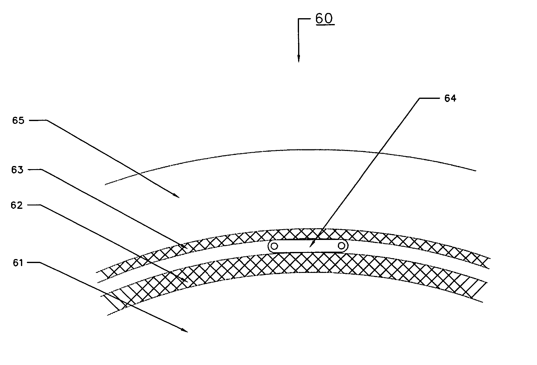
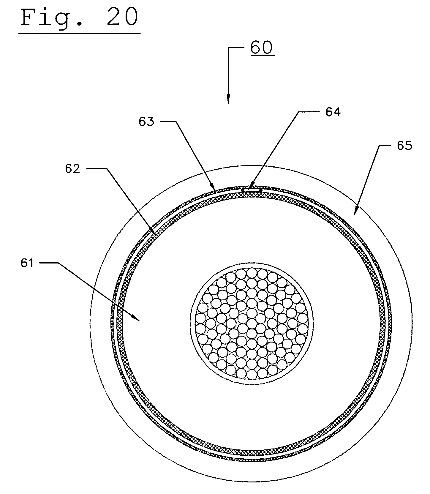
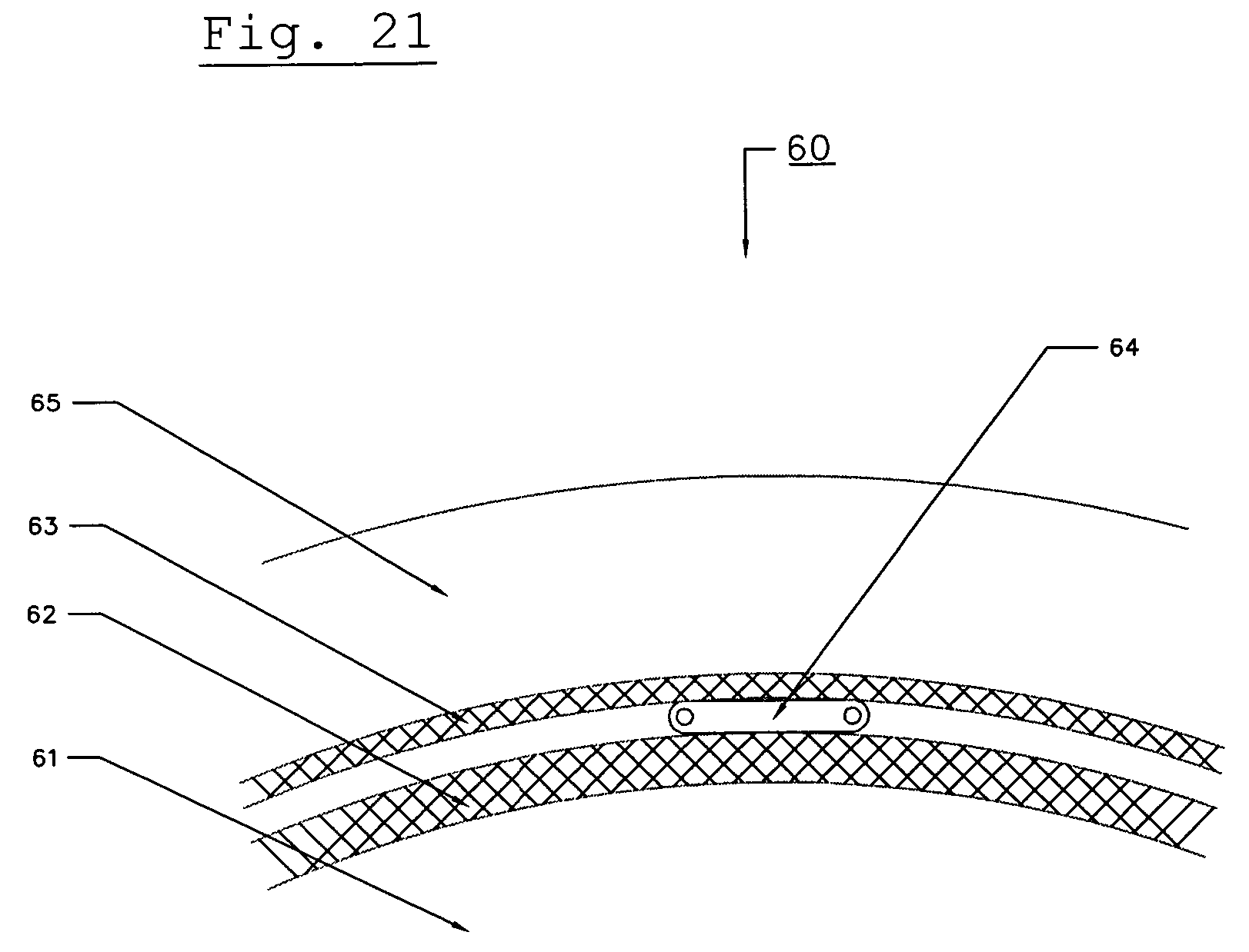
[0037]FIGS. 20 and 21 shows a cross section of a welded corrugate armor shield type high voltage conductor cable (60). FIG. 20 shows a whole cross section of the conductor cable (60), while FIG. 21 shows a partial cross-section of the conductor cable (60). The core (61) of the conductor cable (60) is covered by a layer of insulation / bedding tape (62). The layer of insulation / bedding tape (62) is completely or partially surrounded by a layer of corrugated welded armor (63). The corrugated welded armor is covered by a jacket (65). One holding member (64) is located in between the layer of insulation / bedding tape and the corrugated welded armor (63). The holding member (64) may have oval, circular, or like cross section shape. The holding member can be placed in the conductor cable (60) in a longitudinal fashion or a helically wrapped around the core (61). The holding member (64) can be held in place by a binder string, tape, or other connective means.

[0038]Advantageously an elongated ...


PUM

PropertyMeasurementUnit
Temperatureaaaaaaaaaa
Strengthaaaaaaaaaa
Semiconductor propertiesaaaaaaaaaa

Abstract

An electrical cable having a holding member arranged within the cable for an optic fiber, which can be used for temperature sensing and/or communications. The holding member can replace one or more strands of the cable, be placed inside an interstice of the cable, be placed in between various layers of the cable, or placed in the jacket of the cable. At least one strength member may be adjacent to and/or attached to the holding member to provide additional protection for the optic fiber.

Description

CROSS-REFERENCE TO RELATED APPLICATIONS[0001]This application claims priority to provisional patent application Ser. No. 60 / 409,139, filed Sep. 9, 2002 which is relied on and incorporated herein by referenceBACKGROUND OF THE INVENTION[0002]The present invention relates to an electrical cable with a temperature sensing means, and more specifically, to an electric cable that utilizes an optic fiber temperature sensing means placed longitudinally in the cable and having at least one strength member to provide additional protection for the optic fiber. It is desirable to accurately measure the temperature of a cable because the amount of electrical current that can be carried by a cable is limited by temperature. With accurate information regarding cable temperature, utility companies can make better use of their infrastructure.[0003]It is relatively easy to estimate the temperature of a known conductor cable in a steady state ambient air temperature. In contrast, it is extremely diffic...

Claims


Application Information

Patent Timeline
IPC IPC(8): H01B9/02G02B6/44H01B3/30G01K11/32H01B7/32H01B9/00H01B13/02
CPCG01K11/32H01B9/005H01B7/324G02B6/4416H01B13/0214
Inventor LANCASTER, MARKWILKI, THOMASSANDERS, EUGENE T.HAJRA, KASI
Owner SOUTHWIRE CO LLC
Why Eureka
Try Eureka