
Methods for renaming stack references to processor registers

a processor register and stack reference technology, applied in the field of computer processing systems, can solve the problems of slowing down achievable processor performance, affecting the degree of reordering that can be performed, and memory access incurs a number of costs

Inactive Publication Date: 2006-08-01
LINKEDIN
View PDF9 Cites 29 Cited by
  • Summary
  • Abstract
  • Description
  • Claims
  • Application Information

AI Technical Summary

Benefits of technology

[0031]The problems stated above, as well as other related problems of the prior art, are solved

Problems solved by technology

Unfortunately, memory access incurs a number of costs.
This causes further slowdowns in achievable processor performance by serializing operations when multiple live ranges are assigned to the same memory location.
Thus, limitations are typically imposed on the degree of reordering that can be performed in a superscalar processor, when multiple independent values are assigned to the same memory address.
However, accessing a cache is slower in comparison to accessing processor registers, which represent a higher level in the memory hierarchy of a computer processing system.
However, serializing effects of memory references may also result from the way programs are translated from their source level representation to the actual machine.
Predicting dependencies is necessary because the addresses of load and store operations may be unresolved.
This requires hardware of significant complexity.
Moreover, prediction is used, which is not as accurate as actual decoding of the instruction, and may require expensive repair actions.
Disadvantageously, this buffer is expensive, the required hardware is complex, and the buffer does not consider multiprocessor systems and their consistency requirements.
While this approach is sufficient for in the in-order execution of memory operations in a multiprocessor computing system, out-of-order operation in a multiprocessor system may generate incorrect results.
This results in a complex architecture with potentially severe cycle time impact.

Method used


Image

  • Methods for renaming stack references to processor registers
  • Methods for renaming stack references to processor registers
  • Methods for renaming stack references to processor registers

Examples


Embodiment Construction

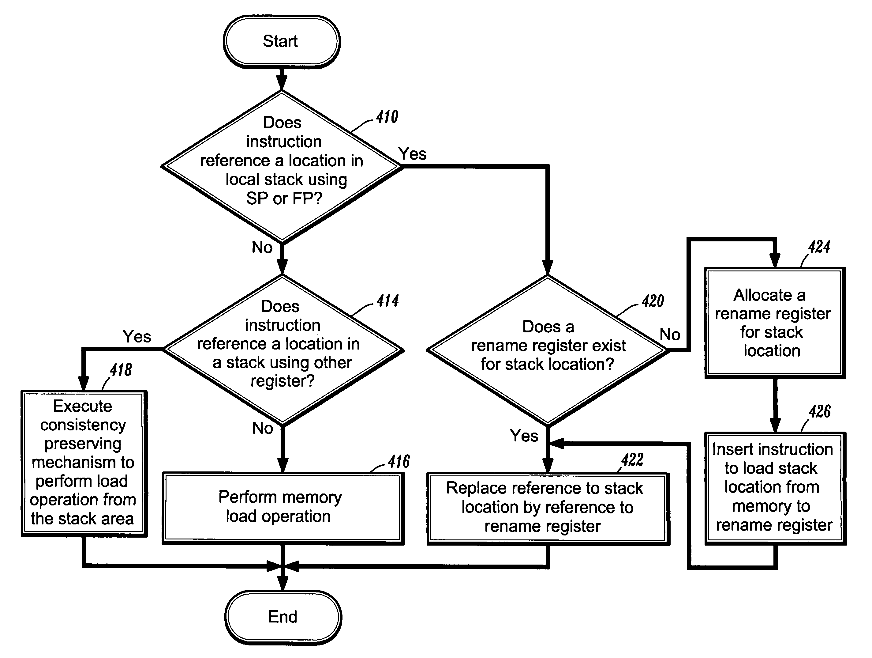
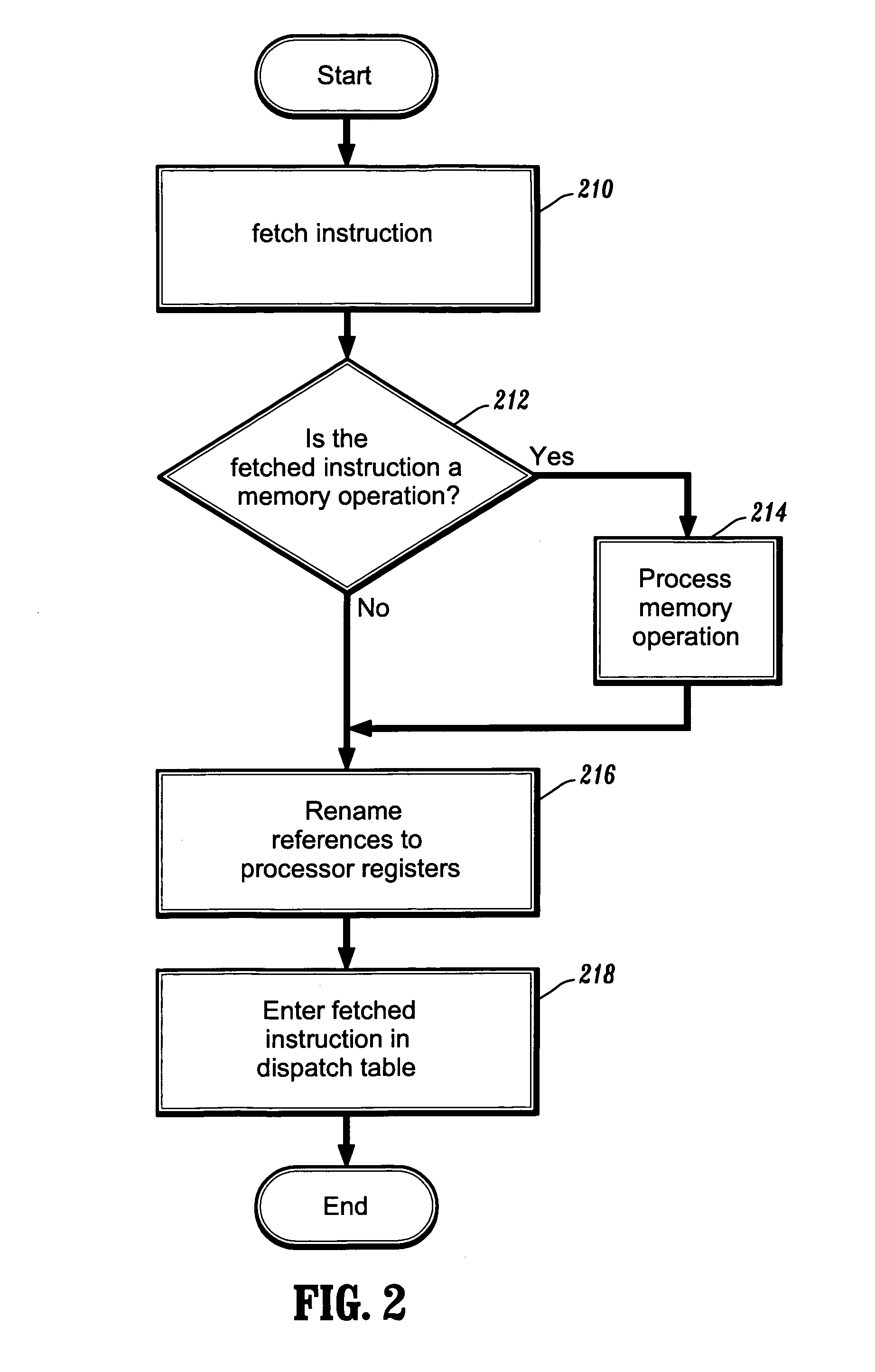
[0047]The present invention is directed to methods for renaming stack references in a computer processing system. According to the invention, the stack references are renamed to processor-internal registers. By concentrating on the frequent rename opportunities for stack references, the renaming architecture can be more efficiently implemented than prior art approaches to renaming memory references.

[0048]Such efficiency is derived from two aspects. With respect to the first aspect, the names are easier to determine, since references to the processor stack use a limited number of addressing registers such as the stack and frame pointers. This reduces the possible ambiguities that can arise in the renaming of memory locations using different general purpose registers. While accesses using other registers are possible, they are sufficiently infrequent to be handled using simple disambiguation techniques.

[0049]With respect to the second aspect, the need to perform consistency-preserving...


PUM


Abstract

According to one aspect of the invention, there is provided a method for renaming memory references to stack locations in a computer processing system. The method includes the steps of detecting stack references that use architecturally defined stack access methods, and replacing the stack references with references to processor-internal registers. The architecturally defined stack access methods include memory accesses that use one of a stack pointer, a frame pointer, and an argument pointer. Moreover, the architecturally defined stack access methods include push, pop, and other stack manipulation operations.

Description

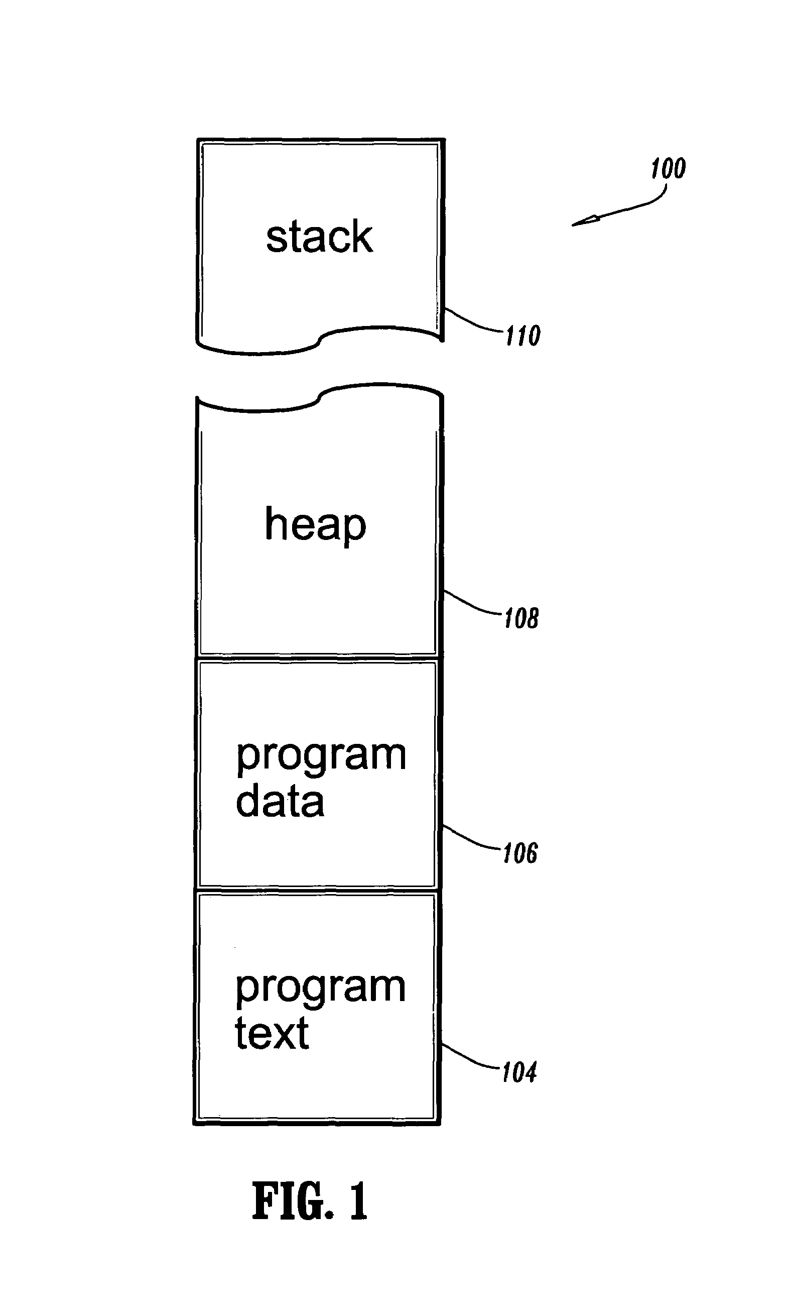
BACKGROUND[0001]1. Technical Field[0002]The present invention generally relates to computer processing systems and, in particular, to methods for renaming stack references in a computer processing system.[0003]2. Background Description[0004]A memory serves as a repository of information in a computer processing system. FIG. 1 is a block diagram illustrating a typical layout of a memory 100 of a computer program according to the prior art. The layout consists of distinct memory areas, including a program text area 104, a program data area 106, a heap 108, and a program stack 110. Program text area 104 is used to store program text (i.e., computer instructions). Program data area 106 is used to store program data (for static data references). Heap 108 is used for dynamically allocated objects and program stack 110 is used for function-local variables.[0005]As shown, memory 100 stores different types of data in distinct memory areas. The following different mechanisms are used to acces...

Claims


Application Information

Patent Timeline
IPC IPC(8): G06F15/00G06F9/38G06F9/30G06F9/312G06F9/34G06F9/40G06F12/00G06F12/02
CPCG06F9/30043G06F9/30134G06F9/3836G06F9/3857G06F9/3838G06F9/3855G06F9/384G06F9/3856G06F9/3858G06F9/3854G06F12/02
Inventor GSCHWIND, MICHAEL K.
Owner LINKEDIN
Learn More