Heat exchanger for industrial installations

a technology for industrial installations and heat exchangers, which is applied in the direction of lighting and heating apparatus, tubular elements, and stationary conduit assemblies, etc. it can solve the problems of heat exchangers that may dissipate or supply energy, exchangers consisting of distributor pipes and cooling webs, etc., and achieves good thermal conductivity, small diameter, and low weight

Inactive Publication Date: 2006-08-08
SPG DRY COOLING BELGIUM
View PDF6 Cites 19 Cited by
  • Summary
  • Abstract
  • Description
  • Claims
  • Application Information

AI Technical Summary

Benefits of technology

[0007]The invention shall thus serve to create a heat exchanger for industrial installations, in particular power plants, allowing smaller diameters and lower weight by means of goo

Problems solved by technology

Generally, heat exchangers may dissipate or supply energy.
In the area of power plants, it has shown as a disadvantage that heat exchangers consistin

Method used


Image

  • Heat exchanger for industrial installations
  • Heat exchanger for industrial installations
  • Heat exchanger for industrial installations

Examples


Embodiment Construction

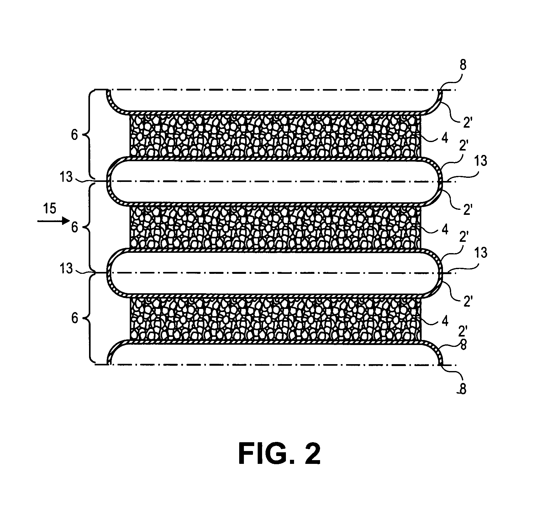
[0028]In the following figures, three constructions of heat exchanger modules for the formation of a heat exchanger of the invention are represented. Herein, the same components are marked with the same reference signs.

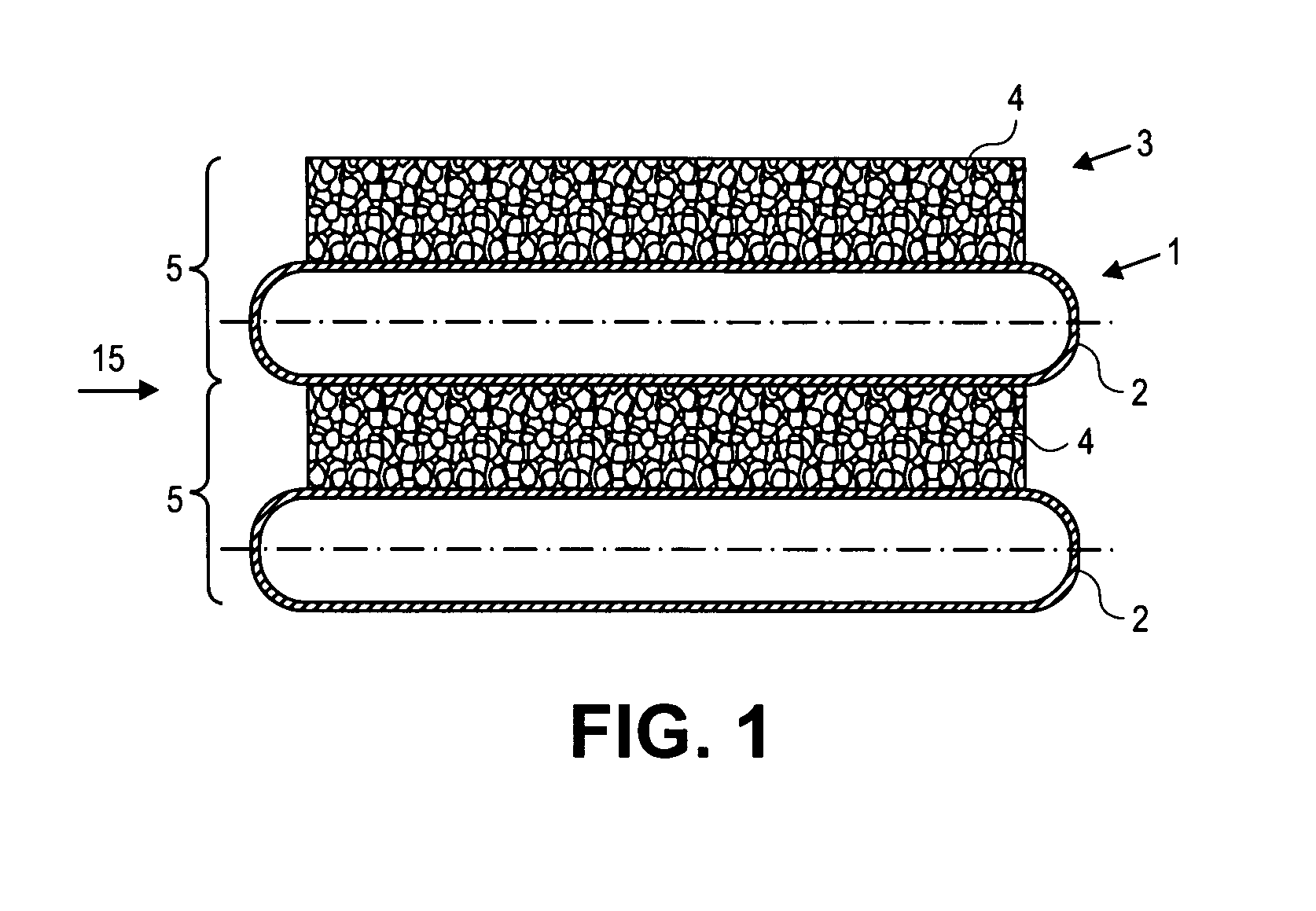
[0029]FIG. 1 shows a cross-section of two stacked sandwich-like heat exchanger modules 5 in a first construction, which are composed of a distributor 1 and a heat exchanger element 3. The distributor 1 is formed by a full pipe 2 with a leveled steel hollow section, which is coated with aluminum. This thin-walled steel hollow section is only a few millimeters thick. As a heat exchanger element 3, a metal sponge 4 of open-pored aluminum foam is foreseen. The metal sponge 4 and full pipes 2 are stacked alternatively over each other and are soldered and welded together. Alternatively, the components of the heat exchanger module 5 may also be agglutinated.

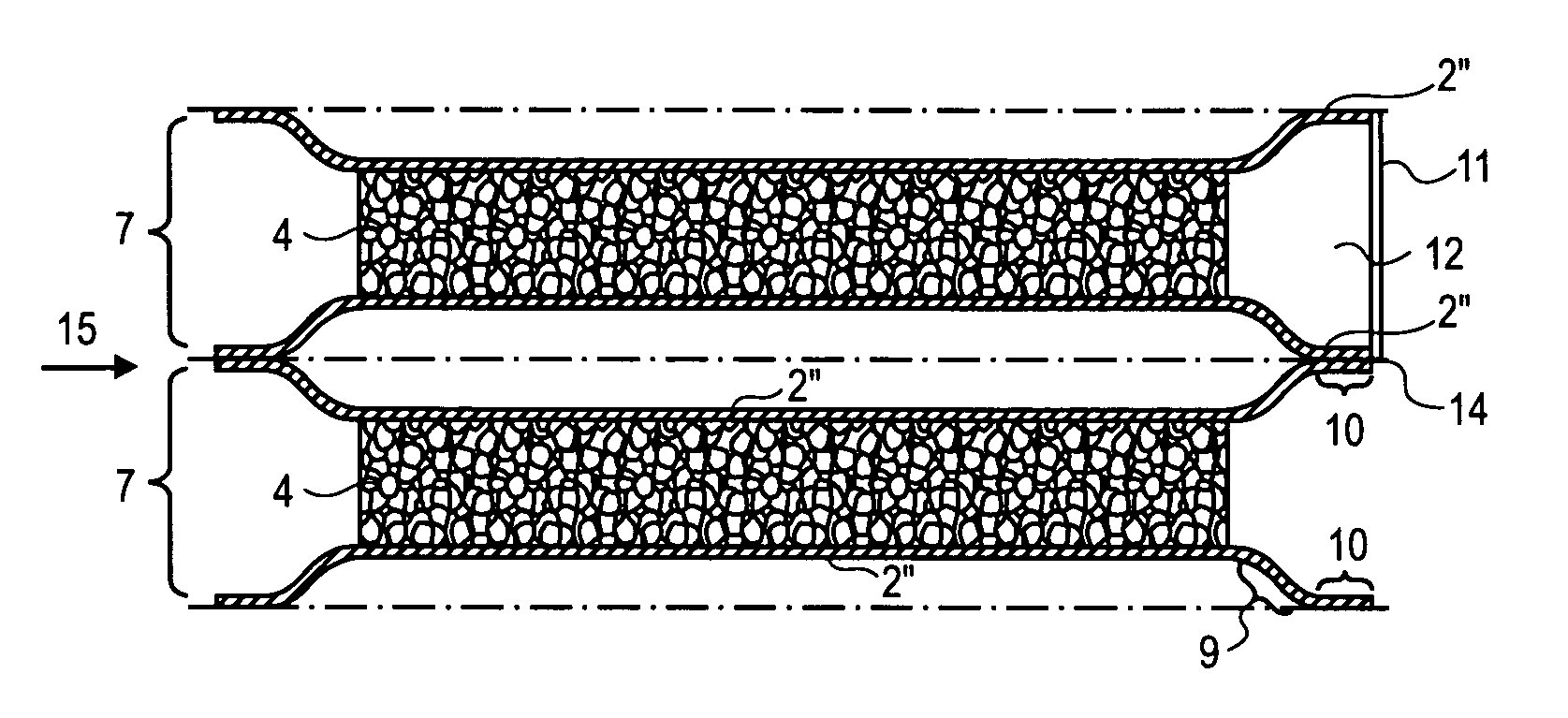
[0030]As may be seen from FIG. 1, the rounded sides of full pipes 2 protrude over the metal sponges 4. Thereby, a suffi...


PUM


Abstract

The invention concerns a heat exchanger for industrial installations, in particular for power plants, with at least one distributor for a fluid medium and at least one heat exchanger element attached to the distributor. The heat exchanger is composed of a sandwich-like configuration of distributors and heat exchanger elements consisting of metal sponges. The distributors are constructed as pipes or at least as semi-pipes connected with each other. Adjacent pipes or semi-pipes are connected with each other through the metal sponge. The sandwich profile of the invention may easily be manufactured in the required dimensions for industrial installations. Herein, particularly the low weight of such a heat exchanger module and the connection between shell and metal sponge, which may simply be made by means of soldering or welding, proves to be particularly advantageous. The metal foam may also be cast onto the shells. The metal sponge should preferably consist of open-pored metal foam and in particular aluminum foam.

Description

CROSS REFERENCE TO RELATED APPLICATIONS[0001]This application claims priority to European Patent Application No. 04000280.0, filed Jan. 8, 2004, titled HEAT EXCHANGER FOR INDUSTRIAL INSTALLATIONS, the disclosure of which is incorporated herein by reference in its entirety.FIELD OF THE INVENTION[0002]The invention concerns a heat exchanger for industrial installations, in particular for power plants, with at least one distributor for a fluid medium and at least one heat exchanger attached to a distributor.BACKGROUND OF THE INVENTION[0003]The heat exchangers known from the power plant area generally consist of a distributor pipe, the exterior surface of which is at least partly covered with a cooling web. Such heat exchangers are used for example as air ventilated condensers. It is also known that heat exchangers are used as a cooling device in industrial installations of the chemical and food industry.[0004]Generally, heat exchangers may dissipate or supply energy. Generally, an ener...

Claims


Application Information

Patent Timeline
IPC IPC(8): F28D1/03F28F1/12F28D1/053F28F3/08F28F13/00
CPCF28F13/003Y10S165/907
Inventor KIENBOCK, MARTINPODHORSKY, MIROSLAV
Owner SPG DRY COOLING BELGIUM
Why Eureka
Try Eureka