Multi-lobed cutter element for drill bit

a cutter element and drill bit technology, applied in drill bits, cutting machines, earth drilling and mining, etc., can solve the problems of increasing the cost of drilling, requiring considerable time, effort and expense, and the process known as the “trip” of the drill string, so as to achieve aggressive cutting structure, increase the strength of drilling, and enhance the effect of rop

Inactive Publication Date: 2006-08-08
SMITH INT INC
View PDF91 Cites 10 Cited by
  • Summary
  • Abstract
  • Description
  • Claims
  • Application Information

AI Technical Summary

Benefits of technology

[0015]Preferred embodiments of the invention are disclosed which provide an earth boring bit having enhancements in cutter element design that provide the potential for increased ROP, as compared with bits employing cutter elements of conventional shape. The embodiments disclosed include cutter elements having aggressive cutting surfaces that have particular application in the nose region of a rolling cone cutter.
[0017]The cutter elements and drill bits described herein provide an aggressive cutting structure and cutter element having multiple cutting edges offering enhancements in ROP given that the cutter's multiple cutting edges will engage and cut the borehole bottom more times per bit revolution than conventional cutter elements having only a single cutting edge (chisel shaped) or the conventional conical cutter having only a relatively blunt cutting surface. Providing a trailing portion behind the forward facing cutting surface and a trailing surface on the trailing position that extends to the cutting edge provides substantial strength to the cutting lobes by buttressing the forward facing cutting surface and lessening the likelihood of the lobe chipping and breaking. Thus, it is believed that the inserts described herein provide a robust and durable cutter element particularly well suited for use in the nose row of a cone cutter on a rolling cone bit.

Problems solved by technology

As is thus obvious, this process, known as a “trip” of the drill string, requires considerable time, effort and expense.
In certain formations, this may result in a core of material that remains uncut and builds up in the center of the borehole, causing the drilling of the borehole to be slower and more costly.

Method used


Image

  • Multi-lobed cutter element for drill bit
  • Multi-lobed cutter element for drill bit
  • Multi-lobed cutter element for drill bit

Examples


first embodiment

[0022]FIG. 3A is a top view of the present invention;

[0023]FIG. 3B is a side view of a first embodiment of the present invention;

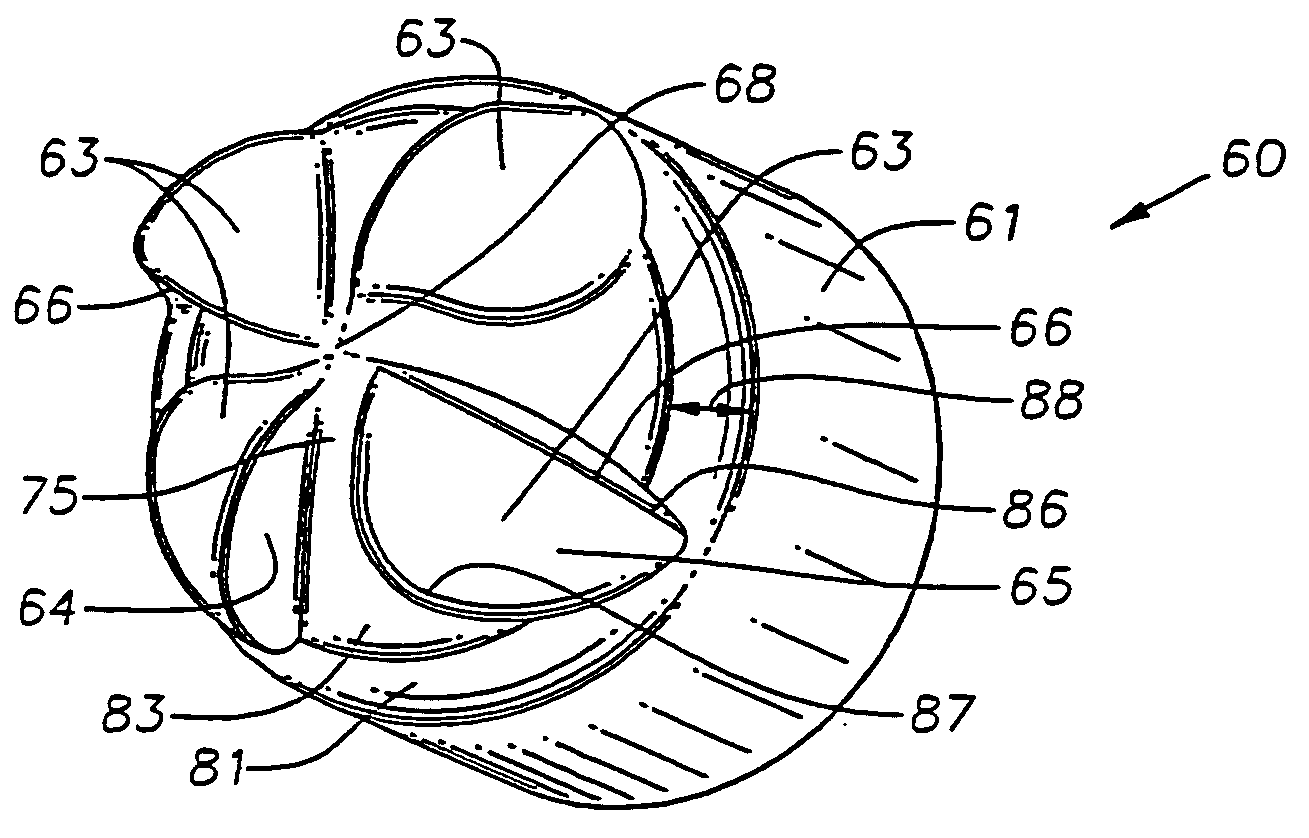
[0024]FIG. 3C is a perspective view of a first embodiment of the present invention;

second embodiment

[0025]FIG. 4A is a top view of the present invention;

[0026]FIG. 4B is a side view of a second embodiment of the present invention;

[0027]FIG. 4C is a perspective view of a second embodiment of the present invention;

third embodiment

[0028]FIG. 5A is a top view of the present invention;

[0029]FIG. 5B is a side view of a third embodiment of the present invention;

[0030]FIG. 5C is a perspective view of a third embodiment of the present invention;

[0031]FIG. 6 is a side view of another embodiment of the present invention;

[0032]FIG. 7 is a side view of another embodiment of the present invention;

[0033]FIG. 8 is a side view of a further embodiment of the present invention; and

[0034]FIG. 9 is a top view of the cutter element shown in FIG. 8.

[0035]FIG. 10 is a top view of still a further embodiment of the present invention.

[0036]FIG. 11A is a top view of a further embodiment of the present invention.

[0037]FIG. 11B is a side view of the cutter element shown in FIG. 11A.

[0038]FIG. 11C is a perspective view of the cutter element shown in FIG. 11A.


PUM


Abstract

Disclosed are cutter elements for a drill bits having particular, but not exclusive, application on the nose portion of the cone cutters of a rolling cone bit. The cutter elements include a base, a cutting portion, and a plurality of cutting lobes extending radially from the cutting portion. Each lobe includes a forward-facing cutting face and trailing portion having a trailing surface that intersects the cutting face in a nonlinear cutting edge. The trailing surface is non-planar and recedes away from the cutting edge. In certain embodiments, the trailing surface is a partial dome shaped surface. The trailing portion provides strength and buttresses the cutting edge.

Description

CROSS-REFERENCE TO RELATED APPLICATIONS[0001]This application is a continuation of U.S. application Ser. No. 10 / 355,493 filed Jan. 31, 2003, entitled “Multi-Lobed Cutter Element for Drill Bit”, incorporated herein by references, issued as U.S. Pat. No. 6,883,624.STATEMENT REGARDING FEDERALLY SPONSORED RESEARCH OR DEVELOPMENT[0002]Not applicable.FIELD OF THE INVENTION[0003]The invention relates generally to earth-boring bits used to drill a borehole for the ultimate recovery of oil, gas or minerals. More particularly, the invention relates to rolling cone rock bits and to an improved cutting structure for such bits. Still more particularly, the invention relates to enhancements in inner row cutter elements.BACKGROUND OF THE INVENTION[0004]An earth-boring drill bit is typically mounted on the lower end of a drill string and is rotated by revolving the drill string at the surface or by actuation of downhole motors or turbines, or by both methods. With weight applied to the drill string...

Claims


Application Information

Patent Timeline
Patent Type & Authority Patents(United States)
IPC IPC(8): E21B10/16E21B10/62E21B10/52
CPCE21B10/52E21B10/16
Inventor MCDONOUGH, SCOTT
Owner SMITH INT INC
Why Eureka
Try Eureka