Rotary jet flow PDC drill bit

A drill bit and jet technology, applied in drill bits, drill pipes, drill pipes, etc., can solve the problems of secondary wear and reduced work efficiency, and achieve the effects of increasing the ROP, prolonging the service life, and reducing the possibility of

Inactive Publication Date: 2016-09-07
YICHANG SHENDA PETROMACHINE +1
12 Cites 17 Cited by

AI-Extracted Technical Summary

Problems solved by technology

[0006] The purpose of the present invention is to overcome the deficiencies of the prior art, and propose a rotary jet PDC drill bit to overc...

Method used

Can determine the quantity and the angle of reverse nozzle flow channel 72 according to above formula, the most preferred reverse nozzle flow channel 72 of present embodiment is 4, the axis of reverse nozzle flow channel 72 and the axis of through hole 71 The incl...

Abstract

The invention relates to drill bits for drilling in the fields of oil-natural gas, mine engineering, building foundation engineering construction, geology and hydrology, in particular to a rotary jet flow PDC drill bit which comprises a drill bit body, knife wings and PDC cutting teeth. The knife wings are positioned at the crown of the drill bit body, the PDC cutting teeth are positioned on the knife wings, a cavity with the lower end open is arranged in the drill bit body, a diversion plate, a compression cavity and a storage cavity are sequentially arranged in the cavity from top to bottom, the compression cavity is communicated with a dendritic runner penetrating the diversion plate, a main body of the dendritic runner is of a hourglass-shaped structure with two ends wide and middle narrow, and a rotating element is arranged in the storage cavity and composed of a rotating element body and rotating blades spirally arranged on the periphery of the rotating element body. The rotary jet flow PDC drill bit is simple in structure and high in impact capability and mechanical drilling speed, secondary abrasion of the drill bit caused by rock debris is avoided, and service life is prolonged; a reverse nozzle joint structure is adopted, so that energy consumption of well drilling is lowered.

Application Domain

Technology Topic

Foundation engineeringHourglass +7

Image

  • Rotary jet flow PDC drill bit
  • Rotary jet flow PDC drill bit
  • Rotary jet flow PDC drill bit

Examples

  • Experimental program(1)

Example Embodiment

[0024] The technical solutions of the present invention will be further described below in conjunction with the drawings and embodiments.
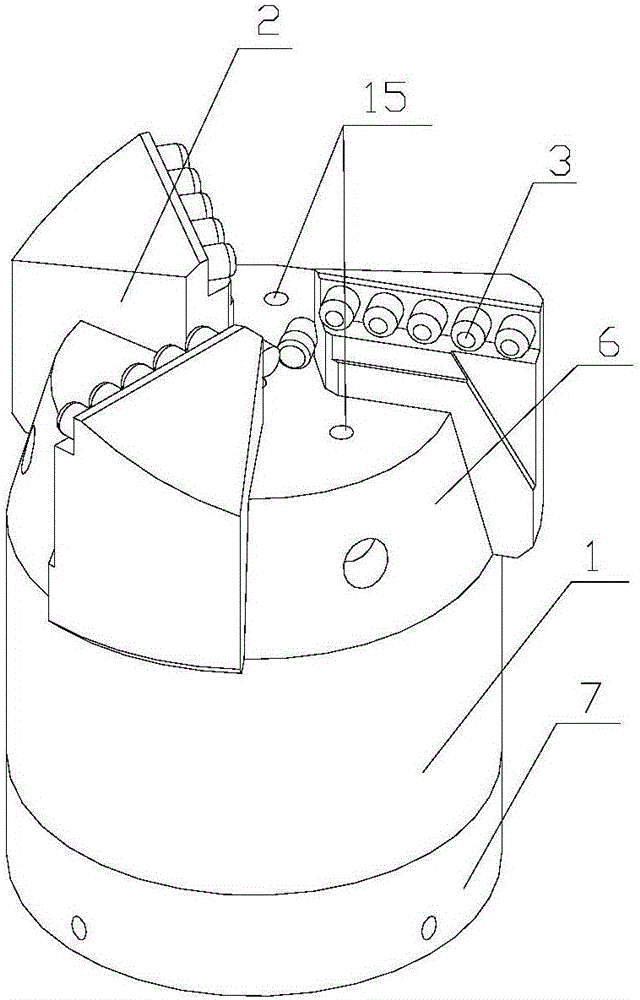
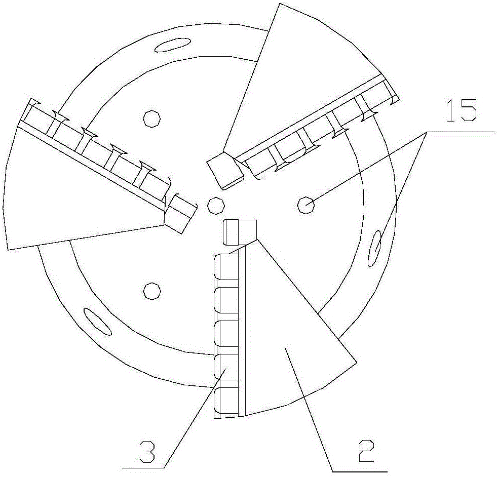
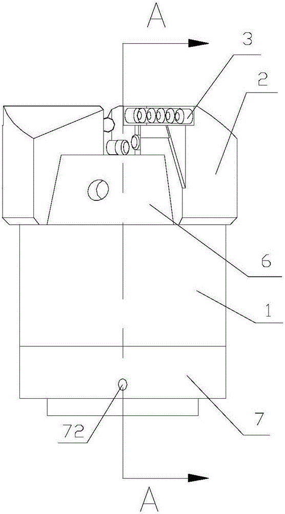
[0025] Such as Figure 1-2 As shown, a rotary jet PDC bit of the present invention includes a bit body 1, a blade 2, PDC cutting teeth 3, a nozzle, a runner, a chip flute 6 and a reverse nozzle joint 7, and the blade 2 is arranged on the bit body 1. In the crown, the PDC cutting teeth 3 are arranged on the blade 2. The runner 5 penetrates the bit body 1 and the reverse nozzle joint 7. The bit body 1 drives the blade 2 to rotate, the PDC cutting teeth 3 cut the rock formation, and then cooperate with the passing flow. The high-pressure jet of the tunnel scoured the remaining cuttings and finally completed the entire drilling operation.
[0026] The structure and principle of the present invention are described in detail below.
[0027] Such as Figure 1-4 As shown, the present invention provides a rotary jet PDC drill bit (PDC or Polycrystalline DiamondCompact bit, polycrystalline diamond composite sheet), which includes a drill body 1 and a plurality of blades 2, the drill body 1 is provided with a through in the axial direction The drill body 1 is provided with a storage cavity 12 inside, the storage cavity 12 is provided with a rotating element 121, and the drill body 1 is also provided with a compression cavity 13 which is located above the storage cavity 12. The compression chamber 13 is in communication with a deflector 14 located inside the bit body 1. A dendritic flow channel 141 is arranged inside the deflector 14, wherein the trunk section of the dendritic flow channel 141 is hourglass-shaped. 141 is in communication with a plurality of water outlets 15 of the drill body 1, and nozzles are arranged at the position of the water outlet 15; wherein, the rear of the drill body 1 is provided with a reverse nozzle joint 7, and the two are fixedly connected. A sealing ring is arranged between the reverse nozzle joints 7, the reverse nozzle joint 7 is also provided with a through hole 71 penetrating in the axial direction, and the reverse nozzle joint 7 is also provided with a plurality of reverse nozzle flow passages. 72. The through hole 71 is in communication with the reverse nozzle flow passage 72, and a nozzle is also provided at the water outlet of the reverse nozzle flow passage 72.
[0028] Specifically, the present invention adopts a flat-bottomed PDC bit with three blades, each blade is provided with a single row of PDC cutting teeth 3, the bit body 1 is a cylinder, and a cavity with a lower opening is provided inside the bit body 1. The storage cavity 12 is provided with a rotating element 121, such as Figure 4 As shown, there are several ways to install the rotating element 121. Simply put it directly into the storage cavity 12 inside the bit body 1, and drive the rotating element 121 to rotate through high-pressure drilling fluid. This embodiment is at the center of the lower end of the rotating element 121 A shaft is fixedly connected, the shaft passes through the through hole 71 and is connected to the motor, and the motor starts the rotation of the rotating element 121; Figure 5 As shown, the rotating element 121 is composed of a rotating element body and rotating blades spirally arranged on the periphery of the rotating element body. Two adjacent rotating blades form a runner. The number of runners in this embodiment is 4, and the drill body 1 is inside. A compression chamber 13 is also provided. After the high-pressure drilling fluid enters the drill bit, the rotating element 121 rotates. The high-pressure drilling fluid is divided into several surges by the spiral blades of the rotating element 121. Each surge flows along the trough and then gradually narrows through both sides. The compression chamber 13 enters the baffle 14 located inside the drill body 1, and the baffle 14 is provided with a branch-shaped flow channel 141. The branch-shaped flow channel 141 is respectively connected with a plurality of water outlets provided on the bit body 1, and the outlet Nozzles are provided at the nozzles. After the high-pressure rotating drilling fluid jet enters the dendritic flow channel 141 of the deflector 14 and flows in the trunk of the dendritic runner 141, the trunk part is in the shape of an hourglass, and the high-pressure rotating drilling fluid jet flows in Through the narrowest part of the hourglass, the dynamic pressure reaches the maximum and the static pressure reaches the minimum. The flow rate of the high-pressure rotating drilling fluid will increase with the change of the cross-sectional area of ​​the gush flow. The entire drilling fluid gush flow must pass through the flow channel at the same time. The process of shrinking, so that the pressure is also reduced at the same time, and then the drilling fluid gush will produce a pressure difference between the two ends of the hourglass. This pressure difference will provide a suction force for the drilling fluid jet, so that the drilling fluid jet can be at a higher flow rate Eject from the water outlet, such as figure 2 The preferred water outlets of this embodiment: 4 axial water outlets and 3 horizontal water outlets; the tail of the drill body 1 is provided with internal threads, and the reverse nozzle joint 7 is provided with external threads, and the two are fixedly connected by threads, In order to prevent leakage, the inner wall of the drill body is also provided with a ring groove, an O-ring is installed on the ring groove, and the reverse nozzle joint 7 is also provided with a through hole 71 that penetrates in the axial direction. The through hole 71 is the water inlet of the drill bit. The reverse nozzle joint 7 is provided with a reverse nozzle flow passage 72, the through hole 71 is in communication with the reverse nozzle flow passage 72, and the water outlet of the reverse nozzle flow passage 72 is provided with a nozzle 4, wherein, due to the high pressure mentioned above The rotating drilling fluid jet has three velocities, namely axial velocity, radial velocity and tangential velocity. The recoil force generated by radial velocity and tangential velocity will cancel each other, and the recoil force generated by axial velocity can be based on The relevant formulas of the reverse injection principle are obtained, such as the momentum equation According to the recoil force, combined with the flow rate and drilling speed requirements, the system resistance is calculated to obtain the motion equation of the nozzle. The formula is cumbersome. Only the variants of the motion equation are listed here:
[0029] m 2 ( x v ) 2 = n Q u n + 1 ( c o s θ - 2 n ) ( x 2 2 - l 0 2 2 ) - m g 2 f 1 l 0 ( x 2 - l 0 2 ) - m g 6 f 2 ( 2 x 3 - 3 l 0 x 2 + l 0 3 )
[0030] f 1 f 2 Is the sliding friction coefficient between the drill bit, nozzle, and drilling material;
[0031] v is the drilling speed of the drill bit;
[0032] Q is the flow rate of the liquid flowing through the nozzle, u is the velocity of the liquid flowing through the nozzle;
[0033] θ is the angle between the nozzle axis and the reverse nozzle joint axis;
[0034] n is the number of front nozzles, and x is the number of reverse nozzle runners;
[0035] According to the above formula, the number and angle of the reverse nozzle flow passages 72 can be determined. The most preferred reverse nozzle flow passages 72 in this embodiment are four, and the angle between the axis of the reverse nozzle flow passage 72 and the axis of the through hole 71 At 20°, through these nozzles 4 arranged at the outlet of the reverse nozzle flow channel 72, the reverse injection principle is used to provide power to assist in driving the PDC bit forward and reduce energy consumption in drilling operations.
[0036] The unspecified part of the present invention is the prior art.
[0037] Finally, it should be noted that the above embodiments are only used to illustrate the technical solutions of the present invention and not to limit them. Although the present invention has been described in detail with reference to the preferred embodiments, those of ordinary skill in the art should understand that the technical solutions of the present invention can be implemented Modifications or equivalent replacements without departing from the purpose and scope of the technical solution of the present invention should be covered by the scope of the claims of the present invention.

PUM

no PUM

Description & Claims & Application Information

We can also present the details of the Description, Claims and Application information to help users get a comprehensive understanding of the technical details of the patent, such as background art, summary of invention, brief description of drawings, description of embodiments, and other original content. On the other hand, users can also determine the specific scope of protection of the technology through the list of claims; as well as understand the changes in the life cycle of the technology with the presentation of the patent timeline. Login to view more.

Similar technology patents

Organic salt weighting agent

PendingCN112760085AInhibition of wellbore fracturesIncrease ROPDrilling compositionCarboxylateOrganic acid
Owner:KARAMAY CITY YIEN TECHN SERVICES

Well drilling method using combination system of screw and rotary guide tool

ActiveCN111550185AIncrease ROPImproved wellbore cleaningConstructionsDirectional drillingPhysicsEngineering
Owner:洲际海峡能源科技有限公司

Classification and recommendation of technical efficacy words

  • Increase ROP
  • Reduce the possibility

Turbo-type underground hydraulic oscillator

ActiveCN106639944AReduce frictionIncrease ROPVibration devicesVibration drillingPetroleumHigh frequency
Owner:YANGTZE UNIVERSITY

Tool and method for drilling, reaming, and cutting

InactiveUS20050183891A1Reduce penetration rateIncrease ROPDrill bitsDrilling rodsInjectorEngineering
Owner:CHRISMAN DAVID SCOTT

Down-hole speed increasing tool with axial impact function

ActiveCN105927144AAlleviate stuck-slip phenomenonIncrease ROPBorehole drivesPistonStator
Owner:沛县昌运机械制造有限公司

Cas9-foki fusion proteins and uses thereof

ActiveUS20150071899A1Strong specificityReduce the possibilityFusion with DNA-binding domainPeptide/protein ingredientsResearch settingNuclease
Owner:PRESIDENT & FELLOWS OF HARVARD COLLEGE

Prosthetic heart valves

InactiveUS20080082163A1Reduce the possibilityGood blood compatibilityHeart valvesProsthesisBiomedical engineering
Owner:ST JUDE MEDICAL LLC
Why Eureka
Try Eureka