Noise attenuation device for a vehicle exhaust system
a technology of noise attenuation device and exhaust system, which is applied in the direction of combustion-air/fuel-air treatment, fuel intake silencer, machine/engine, etc., can solve the problems of unsatisfactory impingement noise, and achieve the effect of reducing noise, reducing turbulence, and reducing nois
- Summary
- Abstract
- Description
- Claims
- Application Information
AI Technical Summary
Benefits of technology
Problems solved by technology
Method used
Image
Examples
second embodiment
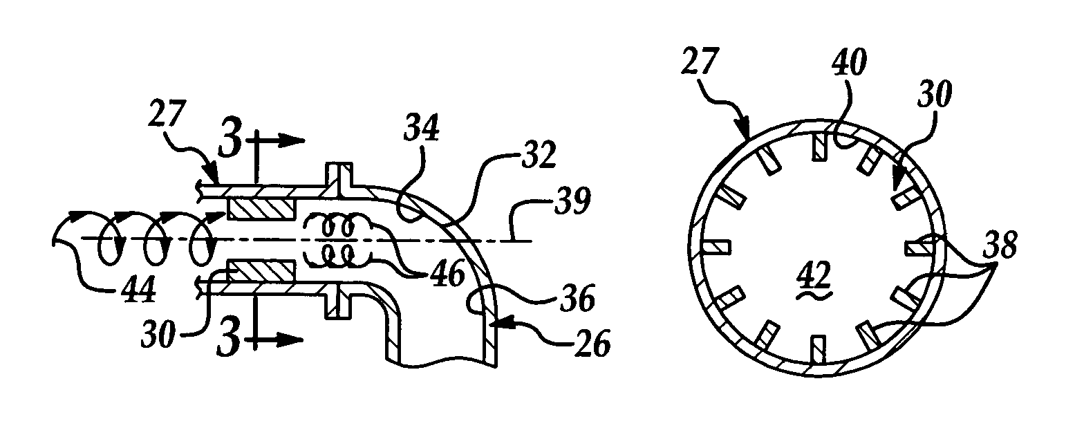
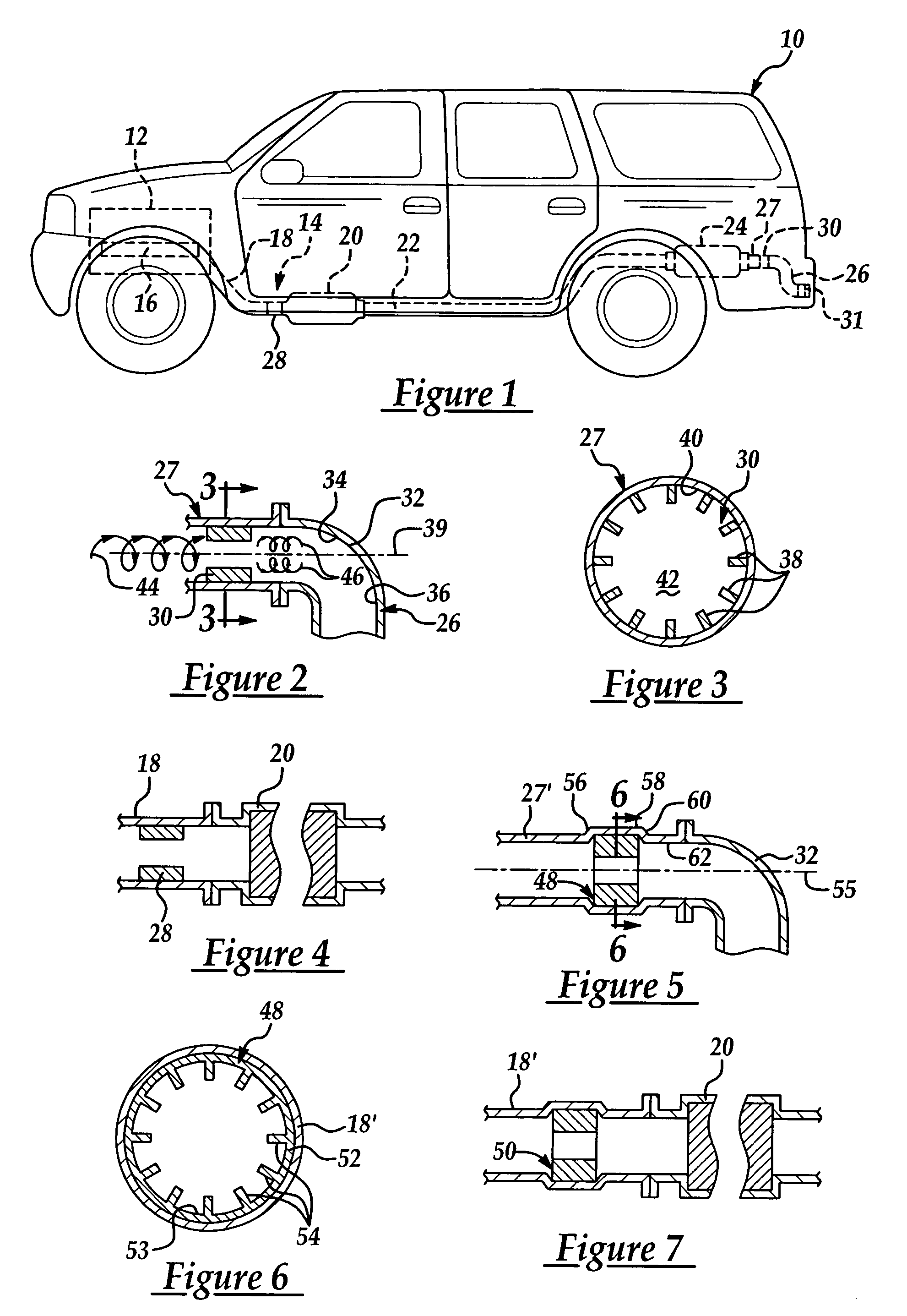
[0036]Referring to FIGS. 5 and 7, the present invention is shown in noise attenuation devices 48, 50. A difference between devices 48, 50 and device 30 is that devices 48, 50 are separate components that can be affixed within exhaust system 14 instead of being formed integral within exhaust pipe sections of exhaust system 14. Referring to FIG. 5, device 48 may be utilized to reduce turbulence in exhaust gases upstream of bend 32 to reduce the impingement noise generated by exhaust gases contacting bend 32. Similarly, referring to FIG. 7, device 50 may be utilized to reduce turbulence in exhaust gases upstream of converter 20 to reduce impingement noise generated by exhaust gases contacting converter 20.
[0037]Referring to FIGS. 5 and 6, device 48 may include a tubular wall 52 and a plurality of vanes 52 extending inwardly from wall 52 a predetermined distance into an aperture 53. Further, vanes 54 may extend from a predetermined axial position on axis 55 a predetermined axial distanc...
third embodiment
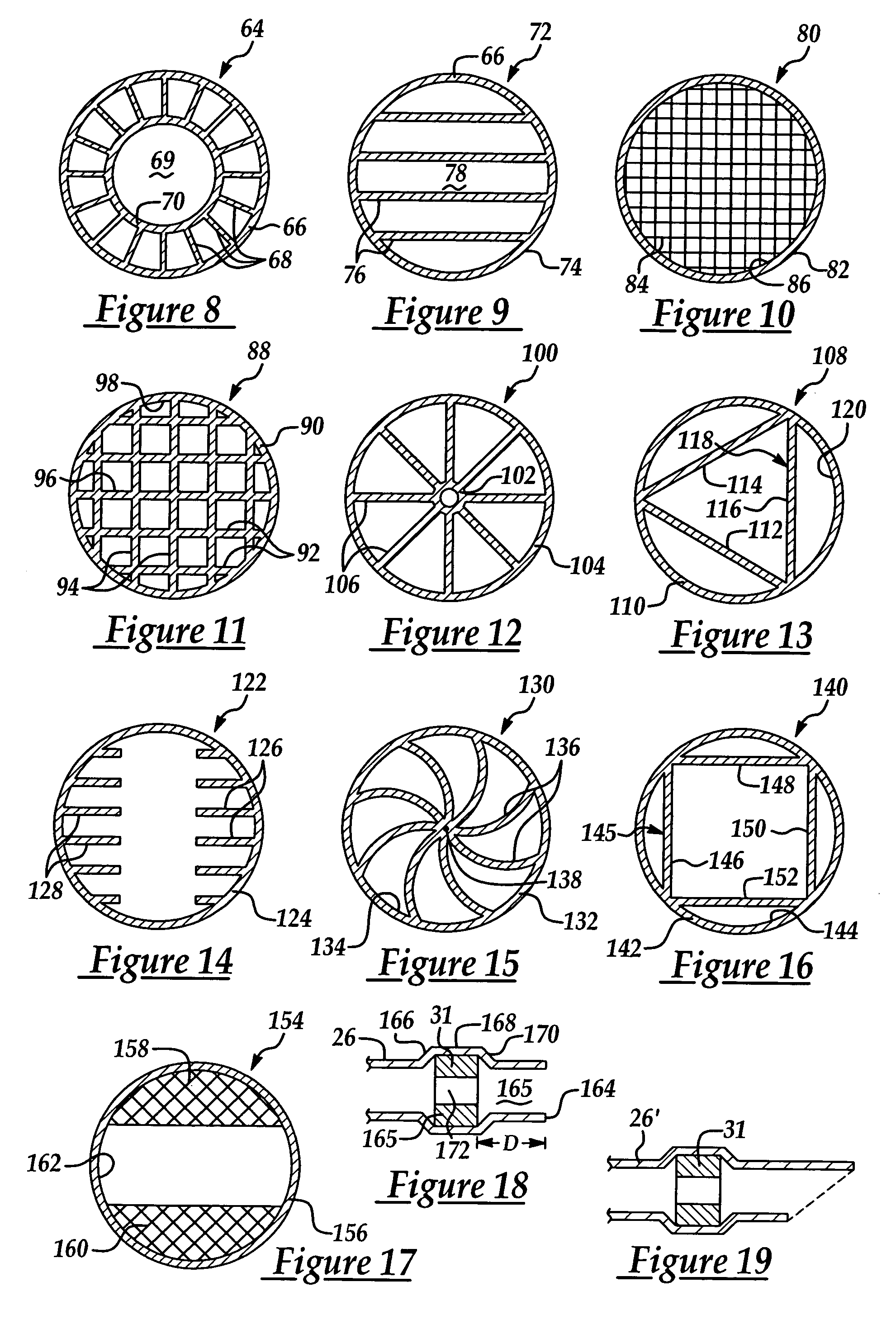
[0039]Referring to FIG. 8, a cross-sectional view of the present invention is shown as noise attenuation device 64. Device 64 may be disposed upstream of a discontinuity in exhaust system 14 to reduce impingement noise in the frequency range of 1000–6000 Hz. As shown, device 64 may include a tubular wall 66 and a plurality of vanes 68 extending radially inwardly from wall 66 into an aperture 69 defined by wall 66. Further, vanes 68 may extend inwardly a predetermined distance and be affixed to an internal ring 70. Further, wall 66, vanes 68, and ring 70 may extend from a predetermined axial position a predetermined axial distance. Device 64 may be press-fit within exhaust system 14 as described above with respect to devices 48, 50. In an alternate embodiment (not shown), vanes 68 could be formed integrally within an exhaust pipe section instead of being attached to wall 66.
fourth embodiment
[0040]Referring to FIG. 9, a cross-sectional view of the present invention is shown as noise attenuation device 72. Device 72 may be disposed upstream of a discontinuity in exhaust system 14 to reduce impingement noise in the frequency range of 1000–6000 Hz. As shown, device 72 may include a tubular wall 74 having a plurality of vanes 76 extending across an aperture 78 defined by wall 74. Further, vanes 76 may be disposed parallel to one another across aperture 78. Device 72 may be press-fit within exhaust system 14 as described above with respect to devices 48, 50. In an alternate embodiment (not shown), vanes 78 could be directly integrally formed within an exhaust pipe section instead of being attached to tubular wall 74.
PUM
 Abstract
Description
Claims
Application Information
 - R&D
- Intellectual Property
- Life Sciences
- Materials
- Tech Scout
- Unparalleled Data Quality
- Higher Quality Content
- 60% Fewer Hallucinations
Browse by: Latest US Patents, China's latest patents, Technical Efficacy Thesaurus, Application Domain, Technology Topic, Popular Technical Reports.
© 2025 PatSnap. All rights reserved.Legal|Privacy policy|Modern Slavery Act Transparency Statement|Sitemap|About US| Contact US: help@patsnap.com


