Brake condition monitoring

a technology for condition monitoring and brakes, applied in brake systems, vehicle components, instruments, etc., can solve the problems of affecting the performance of brakes during service, the cost of carbon-carbon brake discs, and the importance of spares provisioning, so as to reduce the increase in temperature, reduce the torque of brakes, and reduce the effect of rapid deceleration

Inactive Publication Date: 2006-08-08
MEGGITT AEROSPACE
View PDF16 Cites 49 Cited by
  • Summary
  • Abstract
  • Description
  • Claims
  • Application Information

AI Technical Summary

Benefits of technology

[0030]Considering a different scenario, if all the drive tenons on a single rotor disc are broken this will result in the loss of 2 friction surfaces. In such a case, when compared with a brake with all friction surfaces available, the same brake control system inputs of pilot brake demand, brake fluid pressure, brake application time, wheel speed and anti-skid activity will result in a lower brake torque being generated, less rapid deceleration and a lower increase in temperature. Alternatively, if a deceleration regulating autobrake is in operation, it will act to regulate deceleration for a given pilot demand by controlling the brake fluid pressure. Hence, the main effect of the drive tenons of a rotor-disc becoming broken will be an increased brake fluid pressure.

Problems solved by technology

Aircraft brakes, especially those employing carbon-carbon composite materials as the friction discs in a multi-disc arrangement, may suffer damage that can affect the performance of the brake during service.
For example, the high cost of carbon-carbon brake discs and delivery lead times in the order of six months makes provisioning of spares an important issue if inventory and hence working capital is to be minimised.
Thus, the wear during a taxi snub on a cold carbon-carbon brake is similar to that of a full landing.
However, there are several disadvantages with this proposal.
However, a relatively small increase in that applied pressure may be all that is necessary to achieve the desired braking effect for a taxi snub.
The use of an inertial sensor is not able to identify all kinds of braking operation carried out, for example check braking against engine thrust, and it might erroneously identify as a braking application a deceleration due to drag, wind effects or throttling back the engines as a braking application.
In some cases, the existence of excessively inefficient braking is signalled, e.g. by a warning signal to the pilot of an aircraft.

Method used


Image

  • Brake condition monitoring
  • Brake condition monitoring
  • Brake condition monitoring

Examples


Embodiment Construction

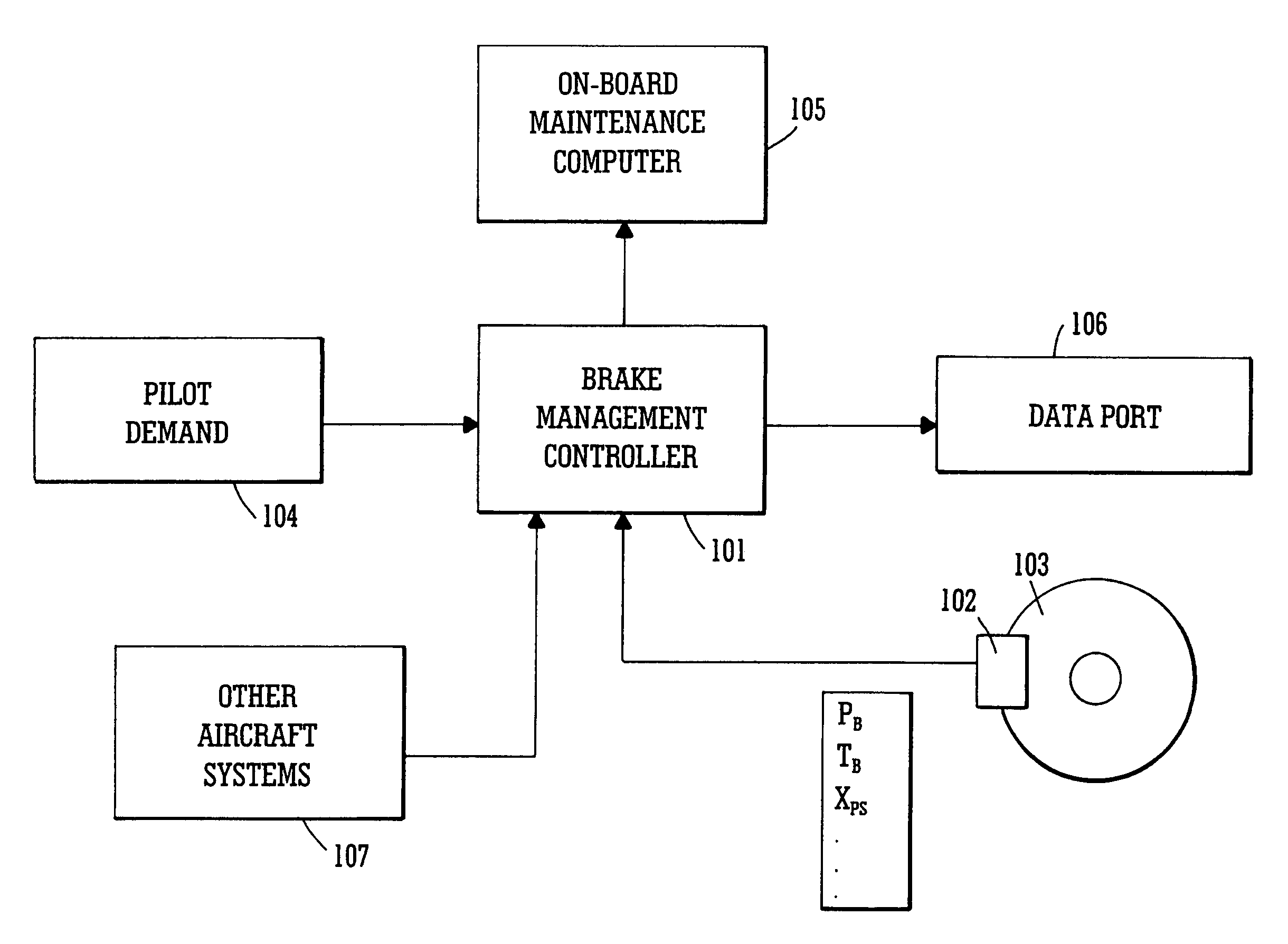
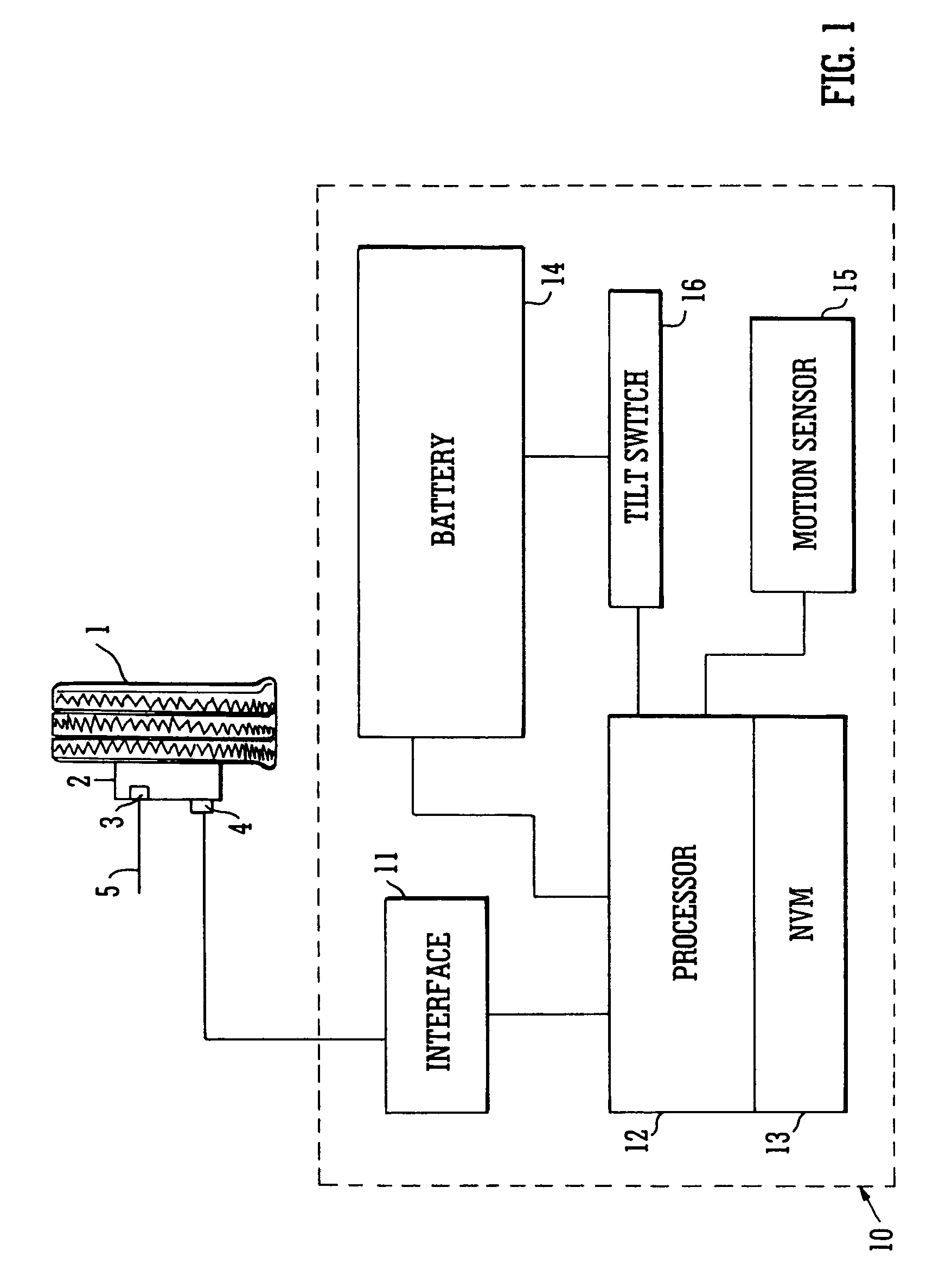
[0038]The system shown in FIG. 1 is applied to one wheel 1 of an aircraft (not shown) having a carbon-carbon multi-disc brake assembly 2 with a hydraulic actuator mechanism 3. Mechanism 3 is driven through line 5 by a hydraulic system of a type containing an ASCU and known in the art. A brake temperature sensing unit 4, typically a thermocouple, is located adjacent the assembly. To record brake usage, the signal from the thermocouple is input to unit 10 via an interface 11 to processor 12 where the signal is processed by an algorithm in known manner to detect when a brake application has been made. The processor output is recorded in the Non Volatile Memory (NVM) unit 13 from which information can be downloaded from a suitable access port (not shown) inside the unit 10 or on an external surface of the unit.

[0039]In order for unit 10 to be able to function independent of other control systems on the aircraft there is provided within unit 10 battery means 14 for providing power to the...


PUM


Abstract

System and method for monitoring the applications of the brakes, e.g. of an aircraft to determine brake condition and operate a brake maintenance programme or charge a brake system user. It is desirable to have accurate information for determining the condition and predicting the life of carbon-carbon brake discs. This is important for safety as well as commercial reasons. The number of landings of an aircraft is often used as a determinant for such as lifetime warranties for brake discs and recommended maintenance periods. However, at least for carbon disc brakes, this may not be entirely accurate. For example such brake discs also wear during taxiing. The system and method herein includes monitoring each actuation of the brakes and making a separate record of each actuation of the brakes in which there is relative movement of the facing friction surfaces that cause wear, and from that separate record determining brake usage. The monitoring may include measuring changes and processing the signals to distinguish between those which fall below and those which are above a threshold value. Herein there is also described, a method and apparatus for monitoring a braking system comprising sensing a plurality of braking parameters having values dependent upon wear in the system and different faults of the system, and identifying and recording wear and faults based on combinations of values of said parameters.

Description

BACKGROUND OF INVENTION[0001]This invention relates to a system and method for monitoring brake applications, more particularly but not exclusively monitoring the application of the brakes of an aircraft, for example, to determine the condition of the brakes. The invention also relates to a system for operating a braking system maintenance programme and to a system for charging a user of a braking system.[0002]Carbon-carbon brake discs are commonly used in aircraft brakes. The service life of a carbon-carbon brake is commonly quoted in terms of the number of landings the brake discs are expected to achieve before replacement, the number of landings being routinely logged for maintenance and airworthiness requirements. The expected number of landings is commonly used as a guarantee of minimum service life for heat packs that are sold or to calculate the cost per brake landing (CBL) where brake heat packs are leased to operators by the brake manufacturers.[0003]Aircraft brakes, especi...

Claims


Application Information

Patent Timeline
Patent Type & Authority Patents(United States)
IPC IPC(8): F16D66/02B64C25/42B60T17/18B60T17/22B64F5/00F16D66/00G06Q40/00
CPCB60T17/22B60T17/221B64C25/42B64F5/0045G06Q40/12F16D66/02F16D2066/001F16D2066/003F16D2066/005F16D2066/006B64F5/60
Inventor MILLER, RICHARD JOHNMARSHALL, ROSS JOHNBAILEY, DAVID ALEXANDERGRIFFIN, NICHOLAS CHARLES
Owner MEGGITT AEROSPACE
Why Eureka
Try Eureka