Supercharge Your Innovation With Domain-Expert AI Agents!

Coupling assembly

a technology of coupling assembly and tube, which is applied in the direction of refrigeration components, light and heating equipment, other domestic objects, etc., can solve the problems of reducing productivity, increasing manufacturing costs, and consuming long preheating time for brazing work, so as to shorten the time for brazing and reduce manufacturing costs

Active Publication Date: 2006-08-08
HIGHLY MARELLI JAPAN CORPORATION
View PDF20 Cites 5 Cited by
  • Summary
  • Abstract
  • Description
  • Claims
  • Application Information

AI Technical Summary

Benefits of technology

[0007]An object of the present invention is to provide a double tube coupling with low manufacturing costs. Another object of the present invention is to provide a double tube coupling which can shorten time for brazing.

Problems solved by technology

Such a formation process incurs an increase in manufacturing costs.
This branched portion has a large thickness, and the brazing work consumes long preheating time and productivity thereby declines.

Method used


Image

  • Coupling assembly
  • Coupling assembly
  • Coupling assembly

Examples


Embodiment Construction

[0035]An embodiment of the present invention will be described with reference to the accompanying drawings.

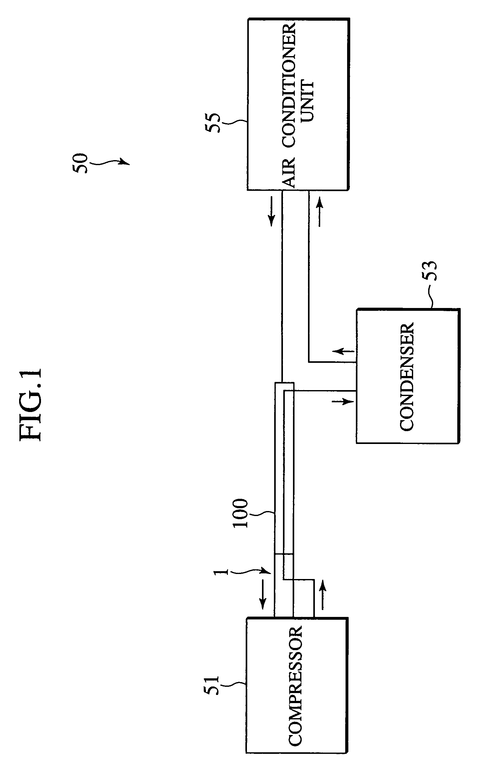
[0036]With reference to FIG. 1, an air-conditioner system 50 is applied to a vehicle, for example. The air-conditioner system 50 includes a compressor 51 configured to compress a refrigerant. The air-conditioner system 50 includes a condenser 53 configured to condense the compressed refrigerant. The air-conditioner system 50 includes an air-conditioner unit 55 configured to cool down, for example, the inside of the vehicle in the condensed refrigerant. The refrigerant absorbing the heat returns to compressor 51. In this system, compressor 51 and condenser 53 are connected together with a double tube 100. The compressor 51 and double tube 100 are connected together with a double tube coupling 1.

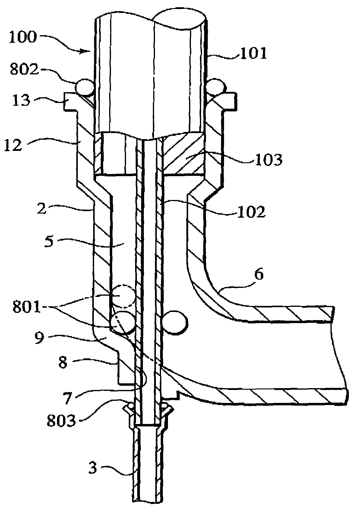
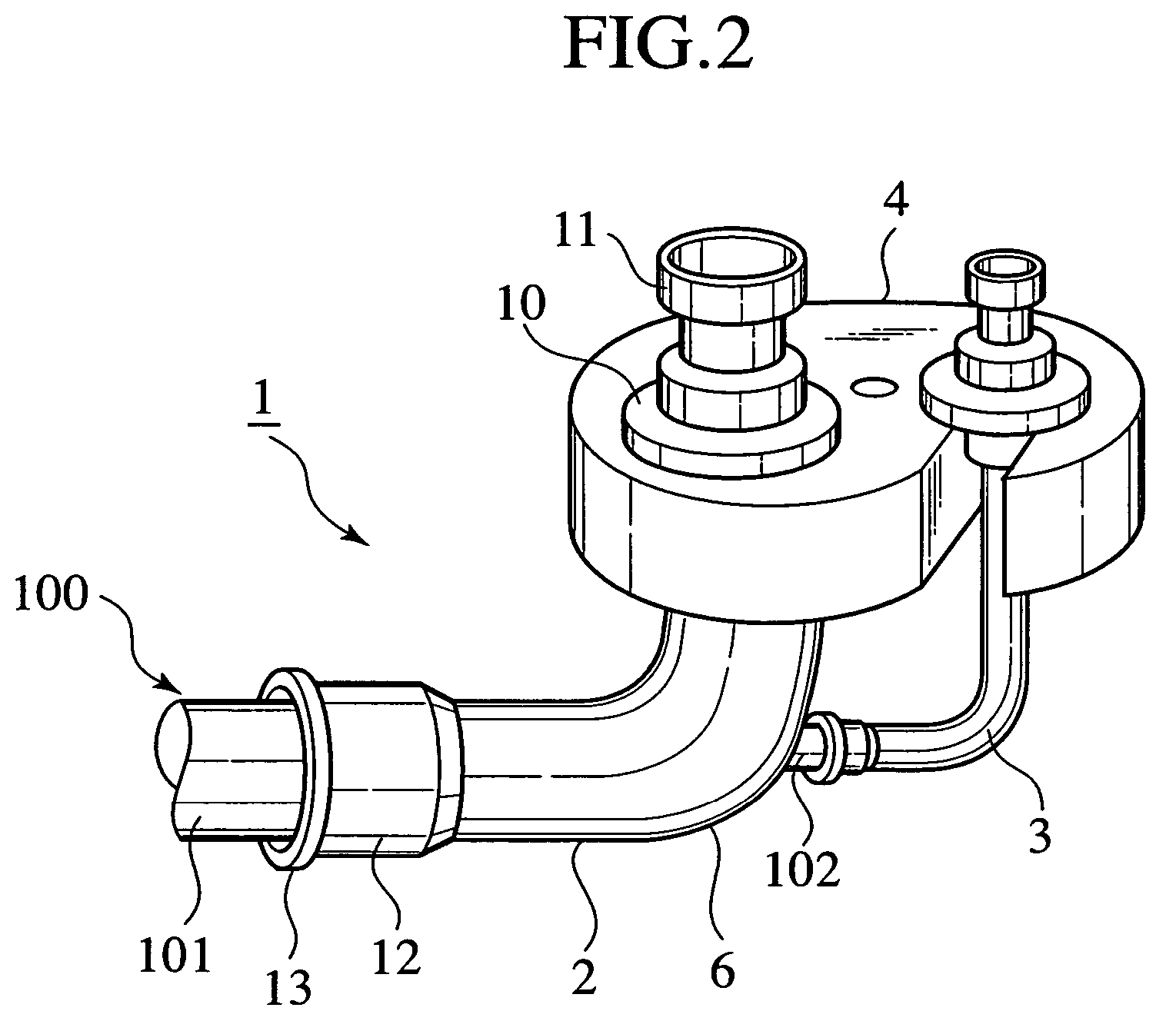
[0037]The double tube coupling 1 shown in FIG. 2 and FIG. 3 is used to connect double tube 100 to a car air-conditioner system or the like. The double tube 100 includes an outer tube 101 ...


PUM

PropertyMeasurementUnit
thicknessaaaaaaaaaa
timeaaaaaaaaaa
inner radial sizeaaaaaaaaaa

Abstract

A coupling for a double tube is configured to connect with the double tube. The double tube includes an outer tube for a first fluid to flow therethrough. The double tube includes an inner tube provided inside of the outer tube and having an end protruding from the outer tube, the inner tube for a second fluid to flow therethrough. The coupling includes a branched portion brazed to an end of the outer tube and brazed to an end of the inner tube, with the end of the inner tube protruding outside through the branched portion. The branched portion is formed as a curved tube having a curved portion. The branched portion has an end joined to an end of the outer tube, with the curved portion having a through-hole for the inner tube to pass therethrough.

Description

CROSS-REFERENCE TO RELATED APPLICATIONS[0001]This application is based upon and claims the benefit of priority from Japanese Patent Application No. 2003-038637 filed on Feb. 17, 2003; the entire contents of which are incorporated herein by reference.BACKGROUND OF THE INVENTION[0002]The present invention relates to a double tube coupling used for connecting a double tube including an outer tube and an inner tube provided inside the outer tube.[0003]A double tube includes an outer tube for circulating a first fluid. This coupling includes an inner tube provided inside the outer tube for circulating a second fluid. The inner tube extends outward from the end of the outer tube.[0004]A double tube coupling includes a first joint for joining the outer tube and a first outside tube each other for guiding the first fluid. The coupling includes a second joint for joining the inner tube and a second outside tube each other by brazing for guiding the second fluid. The coupling includes a branc...

Claims


Application Information

Patent Timeline
Patent Type & Authority Patents(United States)
IPC IPC(8): F16L39/00F16L13/08B21D28/10B21D28/28B21D51/16F25B41/00
CPCF16L39/02F16L39/005B21D39/044B21D39/06
Inventor TAKASAKI, HIROMITAKAMATSU, YOSHIKAZU
Owner HIGHLY MARELLI JAPAN CORPORATION
Features
  • R&D
  • Intellectual Property
  • Life Sciences
  • Materials
  • Tech Scout
  • Unparalleled Data Quality
  • Higher Quality Content
  • 60% Fewer Hallucinations
Learn More