
Combustion method and apparatus for carrying out same

a combustion method and combustion method technology, applied in the direction of combustion types, lighting and heating apparatus, machines/engines, etc., can solve the problems of low energy supply to the fresh fuel/air mixture, not maximizing the velocity, and not maximizing the amount of thermal and kinetic energy injected into the main combustion flow

Inactive Publication Date: 2006-08-08
LEAN FLAME INC
View PDF12 Cites 61 Cited by
  • Summary
  • Abstract
  • Description
  • Claims
  • Application Information

AI Technical Summary

Benefits of technology

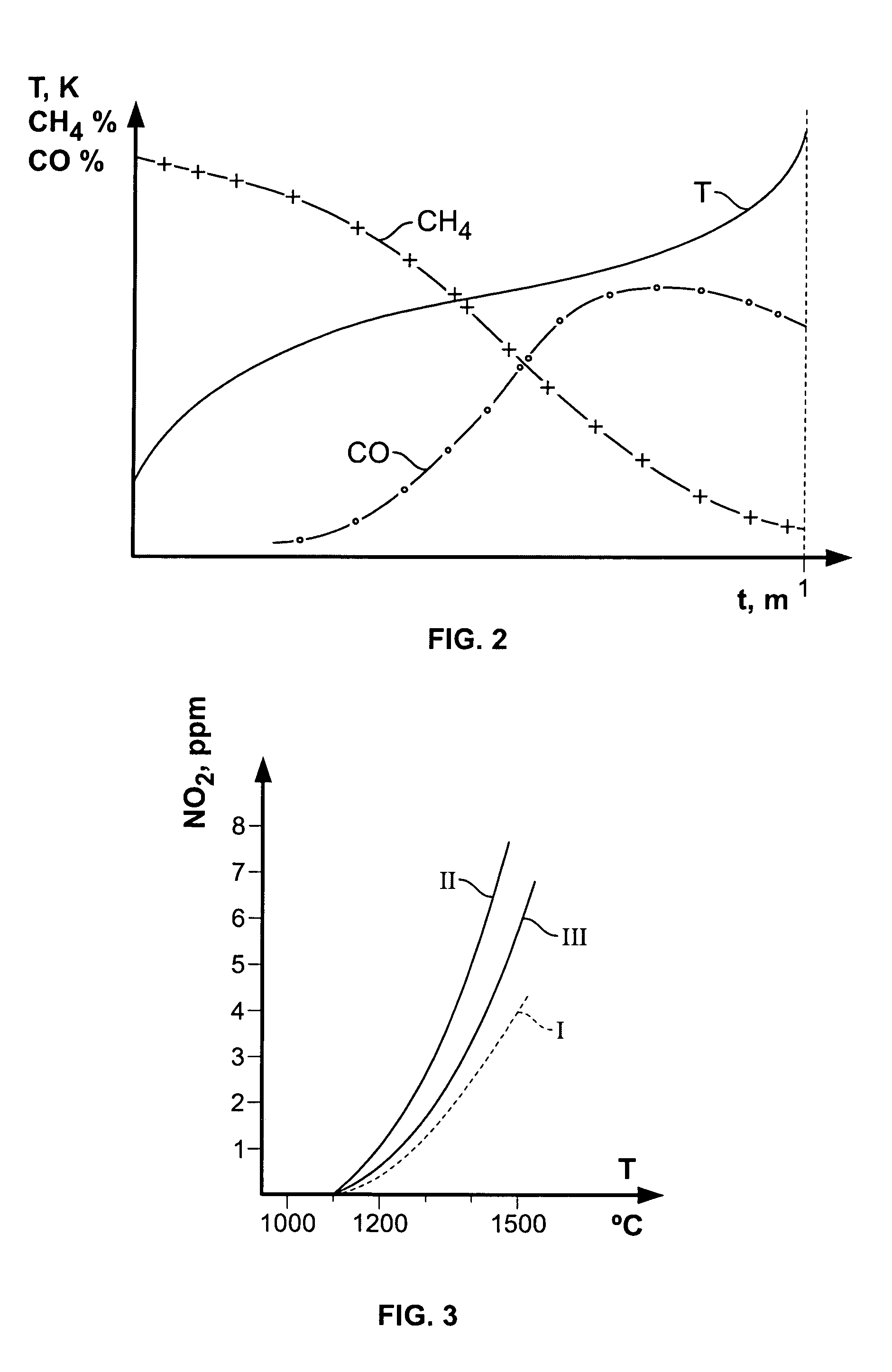
This design enhances the thermal energy transfer, stabilizes combustion across a wide range of fuel / air ratios, reduces emissions, and maintains flame stability even with lean mixtures, while minimizing NOx and CO emissions.

Problems solved by technology

As a result, existing combustors do not maximize the velocity of the recirculation flow, and thus do not maximize the amount of thermal and kinetic energy injected into the main combustion flow, which would be desirable for efficient and reliable combustion of lean and very lean fuel / air mixtures.
However, the recirculation flow (burning gas) that is fed back to the inlet opening zone within the combustion chamber does not have a velocity that is high enough; hence very low energy is supplied to the fresh fuel / air mixture.
Consequently, the conditions for injecting the burning gases into the air flow or into the fuel / air mixture flow are impaired, and the amount of energy supplied by the recirculation flow to the fuel / air mixture is low.
The solution is to make the fuel / air mixture richer, which is not desirable because it results in a higher combustion temperature, incomplete combustion, and increased harmful emissions.
Like Howald, the combustor disclosed by Kydd does not maximize the velocity of the recirculation flow, thus resulting in a low level of energy being supplied to the main combustion flow.
In addition, the combustor in Kydd includes a baffle in the form of an annular plate with holes, so the burning gases do not directly flow into the fresh fuel / air mixture, thereby impairing the conditions for injecting the burning gases into the fuel mixture.
The main disadvantage here is thorough mixing, with the fuel and air mix admitted and thoroughly mixed with almost completely burned gases that are in a swirl motion.
In this case, adding air and / or fuel to the recirculated hot gases is counterproductive because the temperature of the recirculated hot gases will be already lowered before they meet the main flow.
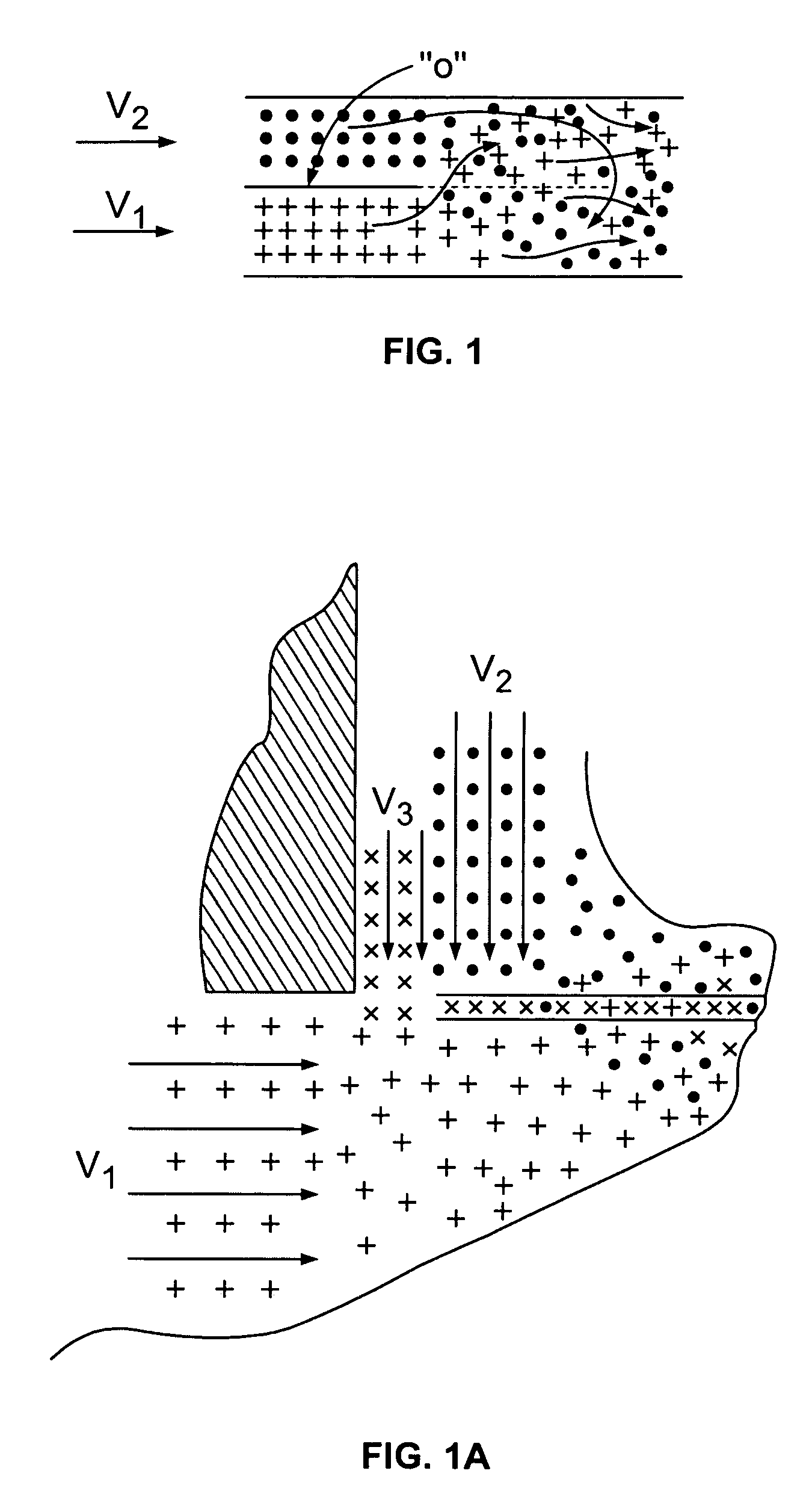
This geometry of mixing of the two flows is very disadvantageous, because the “mild” conditions at collision of the two flows result in a very poor energy transfer between the flows, and non-uniformity or temperatures at the main flow inlet can reach up to 100%, and the inner layers of the incoming main flow may not be heated at all.
This results in poor heating of the incoming main flow with the resulting flameout.
The consequence of this is high non-uniformity of combustion temperature axially along, and radially of the combustor, which translates into lower flame stability when the fuel and air mixture becomes leaner and also to high CO and NOx emissions.
It should be added that the use of additional air and / or fuel inlets in the path of the recirculation flow is very disadvantageous because they create non-uniformity of the velocity profile within the recirculation flow, which translates into increased non-uniformity of energy transfer between the recirculated hot gases and the incoming main flow.
This design has the same disadvantages as those described above.
This is done because the main flame stability could not be achieved in the prior art without using additional devices.
The main flow undergoes sudden expansion, which results in a velocity decrease.
All these factors do not allow additional energy to be supplied to the incoming main flow.
On the other hand, the superficial heating cannot result in any dramatic improvement of flame stability and emission reduction.
Admitting fuel to the hot recirculated gas results in a very non-uniform conditions for combustion because a very small quantity of fuel cannot be mixed thoroughly with a very large quantity of the recirculated gases and secondary air.
Fuel reforming will be very intense and non-uniform in this case with the ensuing cooling.
It is not possible to heat the main flow at the inlet uniformly over the entire cross-section because the result depends entirely on the turbulent mixing of the two flows, which cannot assure uniform mixing through the entire volume.
This reliance on the turbulent (mechanical mixing) is all the more questionable because the two flows move practically co-currently.
First, CO emissions will increase.
Second, more combustion products will have to be added to the incoming flow in order to increase the incoming flow temperature, which causes an increase in fuel reforming, thus bringing temperature down.
Therefore, the use of trapped vortex and recirculated flow in the prior art combustors, while bringing about certain improvement in flame stability and emission performance, has not been able to result in any breakthrough.

Method used


Image

  • Combustion method and apparatus for carrying out same
  • Combustion method and apparatus for carrying out same
  • Combustion method and apparatus for carrying out same

Examples


Embodiment Construction

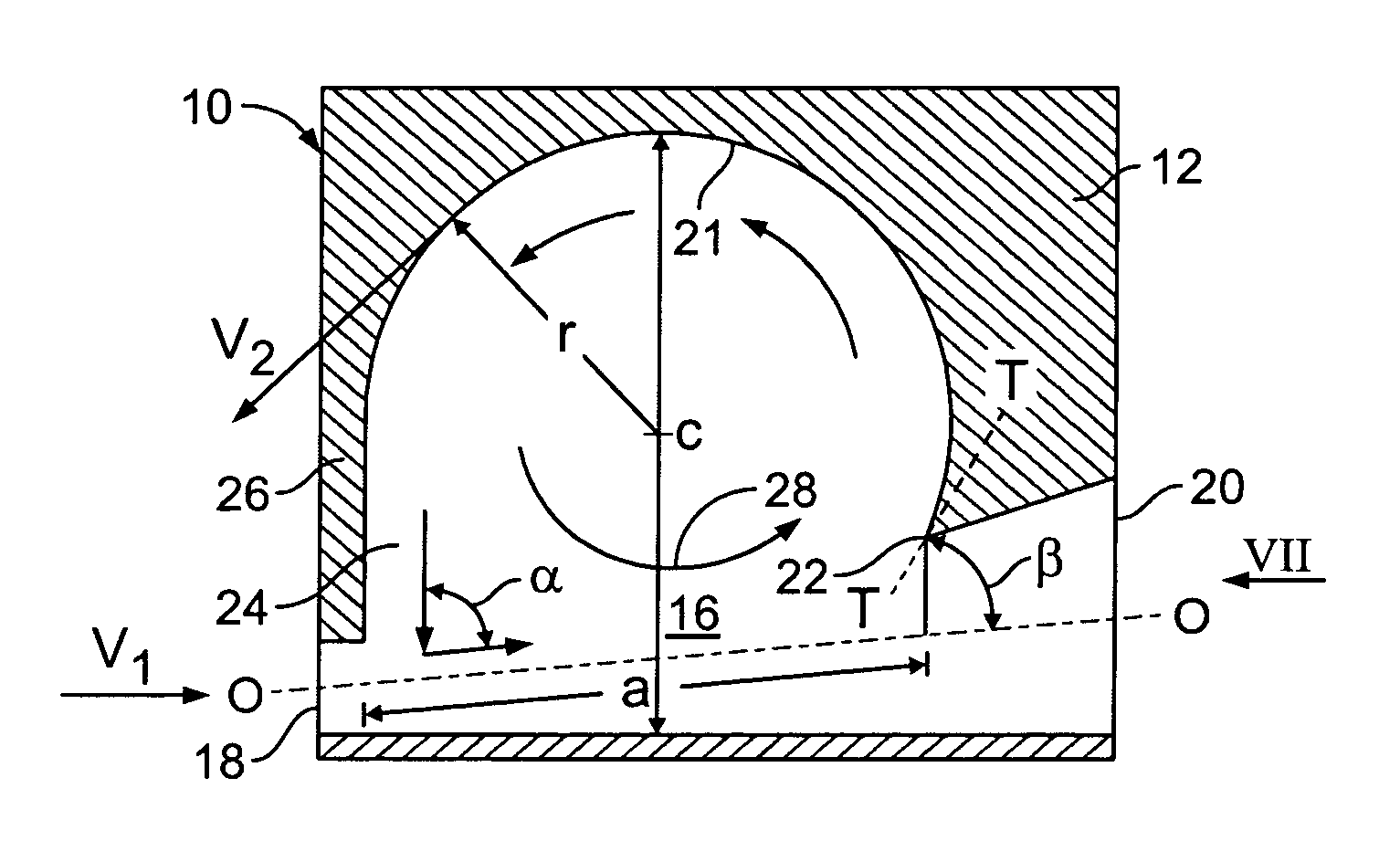
[0044]The invention will now be described in further detail and with reference to the accompanying drawings, illustrating non-limiting exemplary embodiments of the combustor according to invention.

[0045]As a preliminary matter, we provide some definitions for purposes of understanding this specification and the claims.

[0046]

Flamea thin area where chain oxidation reaction isCombustionstarting a chain reaction of fuel oxidation.Inflammation (orthe beginning stage of a chain oxidation reaction.firing, as in the usage“to be fired”)Flamelessthe phenomenon of the occurrence of oxidationcombustionreactions uniformly throughout the volume of themain flowReactordevice for the chemicalreaction realization

[0047]This specification generally uses the term “combustor” to refer to the apparatus described herein, although, as will be described, apparatus in accordance with the invention may be operated under conditions that favor fuel reformation rather than combustion. The term “reactor” is someti...


PUM


Abstract

The invention relates to recirculation flow combustors having a generally curved recirculation chamber and unobstructed flow along the periphery of the boundary layer of the vortex flow in this chamber, and methods of operating such combustors. Such combustors further have a border interface area of low turbulence between the vortex flow and the main flow in the combustor, in which chemical reactions take place which are highly advantageous to the combustion process, and which promote a thermal nozzle effect within the combustor. A combustor of this type may be used for burning lean and super-lean fuel and air mixtures for use in gas turbine engines, jet and rocket engines and thermal plants such as boilers, heat exchanges plants, chemical reactors, and the like. The apparatus and methods of the invention may also be operated under conditions that favor fuel reformation rather than combustion, where such a reaction is desired.

Description

CROSS-REFERENCE TO RELATED APPLICATIONS[0001]This application claims the benefit of U.S. Provisional Application No. 60 / 508,405, filed on Oct. 3, 2003, and U.S. Provisional Application No. 60 / 585,958, filed Jul. 6, 2004.BACKGROUND OF THE INVENTION[0002]1. Field of the Invention[0003]The invention relates to a combustion apparatus and method for burning fuel in a mixture with air with the aim of producing hot gas for various applications. More specifically, the invention relates to a combustion apparatus and method using a combustor with recirculation flow. The invention further relates to an apparatus and method for igniting and burning a mixture of fuel and air. A combustor of this type may be used for burning lean and super-lean fuel and air mixtures for use in gas turbine engines, jet and rocket engines and thermal plants such as boilers, heat exchanges plants, chemical reactors, and the like. The apparatus and methods of the invention may also be operated under conditions that f...

Claims


Application Information

Patent Timeline
Patent Type & Authority Patents(United States)
IPC IPC(8): F23C9/00F23M9/00F02C3/00F23C3/00F23R3/42F23R3/52
CPCF23C3/00F23C9/006F23R3/52F23R3/42F23C2900/03002F23C9/00F23R3/00
Inventor RAKHMAILOV, ANATOLY M.RAKHMAILOV, ANATOLY A.
Owner LEAN FLAME INC
Learn More