Self reference type distance measuring method and distance measuring apparatus using an optical pulse

a distance measurement and self-referential technology, applied in the direction of distance measurement, pulse technique, horology, etc., can solve the problems of inability to accurately measure, the cost of processing such signals by means of an ordinary signal processing circuit without saturation will be prohibitive if technologically possible, and the difference in the arrival time can be accurately determined

Inactive Publication Date: 2006-08-08
OLYMPUS CORP
View PDF4 Cites 11 Cited by
  • Summary
  • Abstract
  • Description
  • Claims
  • Application Information

AI Technical Summary

Benefits of technology

[0009]Therefore, it is the object of the present invention to provide a distance measuring method and a distance measuring apparatus of the self reference type adapted to accurately de...

Problems solved by technology

However, the method of U.S. Pat. No. 5,726,742 of comparing the received signal with a delayed signal by means of a comparator is accompanied by a problem that the comparator is required to operate beyond its normal operation range particularly when the received signal shows large fluctuations of level or becomes saturated to make it no longer possible to accura...

Method used


Image

  • Self reference type distance measuring method and distance measuring apparatus using an optical pulse
  • Self reference type distance measuring method and distance measuring apparatus using an optical pulse
  • Self reference type distance measuring method and distance measuring apparatus using an optical pulse

Examples


Embodiment Construction

[0031]Reference will now be made in detail to the presently preferred embodiment of the invention as illustrated in the accompanying drawings, in which like reference characters designate like or corresponding parts throughout the several drawings.

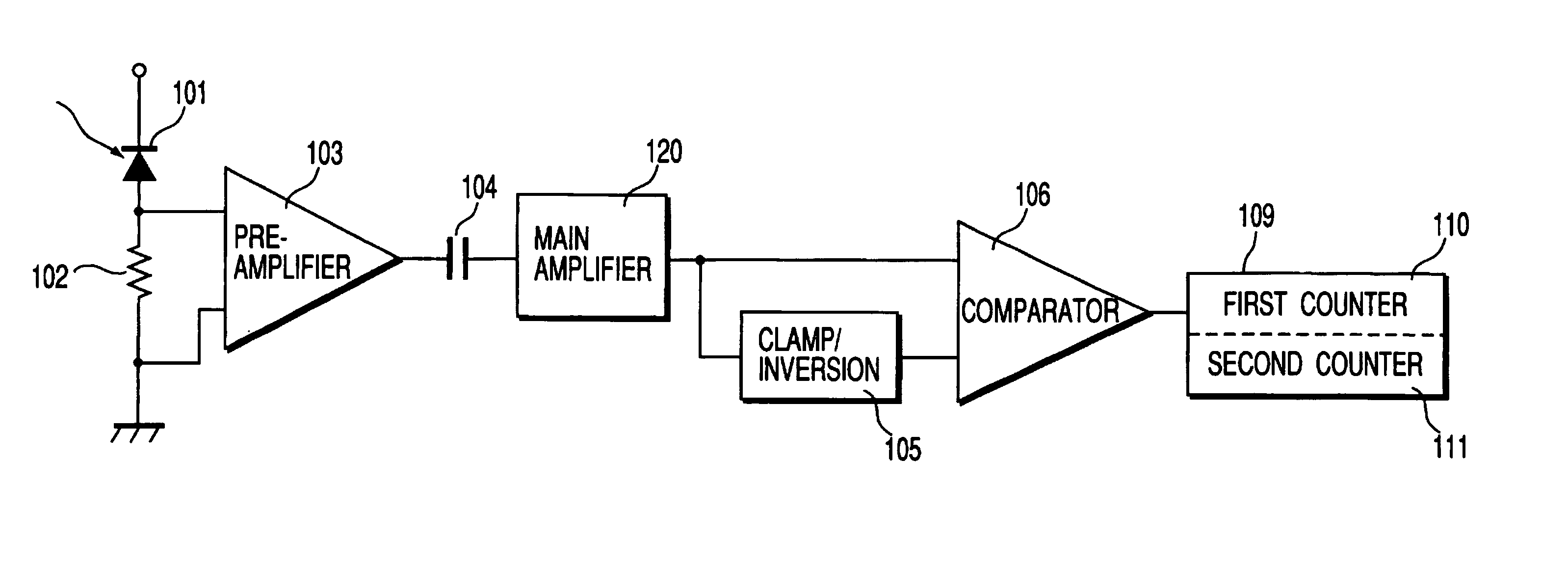
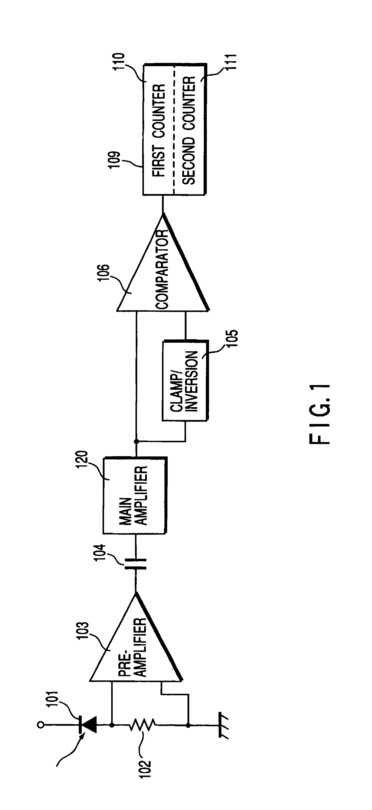
[0032]FIG. 1 is a schematic block diagram of an embodiment of distance measuring apparatus according to the invention.

[0033]In FIG. 1, reference symbol 101 denotes a light receiving element to be used for photoelectric conversion.

[0034]Reference symbol 102 denotes a resistor connected in series to said light receiving element 101.

[0035]Reference symbol 103 denotes a pre-amplifier connected to the opposite ends of said resistor 102 for current / voltage (I-V) conversion (to be referred to as pre-amp hereinafter).

[0036]Reference symbol 104 denotes a capacitor connected to the output terminal of said pre-amp.

[0037]Reference symbol 105 denotes a clamp / inversion circuit connected to main amplifier 120.

[0038]Reference symbol 106 denotes a comparat...


PUM


Abstract

A distance measuring apparatus measure the distance to a target by measuring the time required for an emitted beam of light to go to and return from the target. The light receiving section of the apparatus converts the received light into an electric signal. The clamp/inversion section of the apparatus clamps and inverts the output of the light receiving section. The comparing section of the apparatus compares the output of the light receiving section and the output of the clamp/inversion section. The determining section of the apparatus identifies the time of receiving the light on the basis of the outcome of the operation of the comparing section.

Description

BACKGROUND OF THE INVENTION[0001]This invention relates to a distance measuring method and a distance measuring apparatus and, more particularly, it relates to a distance measuring method and a distance measuring apparatus for measuring the distance to a target by shooting the target with an optical pulse and measuring the time required for the optical pulse to go to and return from the target.[0002]In the above identified technological field, there has been known methods for detecting the arrival time of a received optical pulse from a target by detecting the intersection of the received signal and a signal obtained by delaying it (referred to as self-reference type method).[0003]U.S. Pat. No. 5,726,742 discloses such a self reference type method.[0004]With the method of U.S. Pat. No. 5,726,742, a received signal is divided into two signals and one of them is delayed by means of a delay element. Then, the other one of the two signals is compared with the delayed signal by means of ...

Claims


Application Information

Patent Timeline
IPC IPC(8): G04F8/00G01C3/08G01S13/08H03K5/22G01C3/06G01S17/10G01S7/4861G01S7/4865H03F3/08H03K5/08
CPCG01S7/4861G01S7/4865H03K5/082H03F3/087G01S17/10
Inventor KATO, MASAHIKO
Owner OLYMPUS CORP
Why Eureka
Try Eureka