Dither stripper with non-linearity correction

a dither stripper and non-linearity technology, applied in the direction of speed measurement using gyroscopic effects, instruments, surveying and navigation, etc., can solve the problems of gain and phase shift disturbance, affecting the stability of any control loop or any readout signal processing system, and unsatisfactory phenomena, so as to improve the quality of dither pickoff signals and improve the accuracy of gyro output signals. , the effect of less error

Active Publication Date: 2006-08-08
HONEYWELL INT INC
View PDF9 Cites 2 Cited by
  • Summary
  • Abstract
  • Description
  • Claims
  • Application Information

AI Technical Summary

Benefits of technology

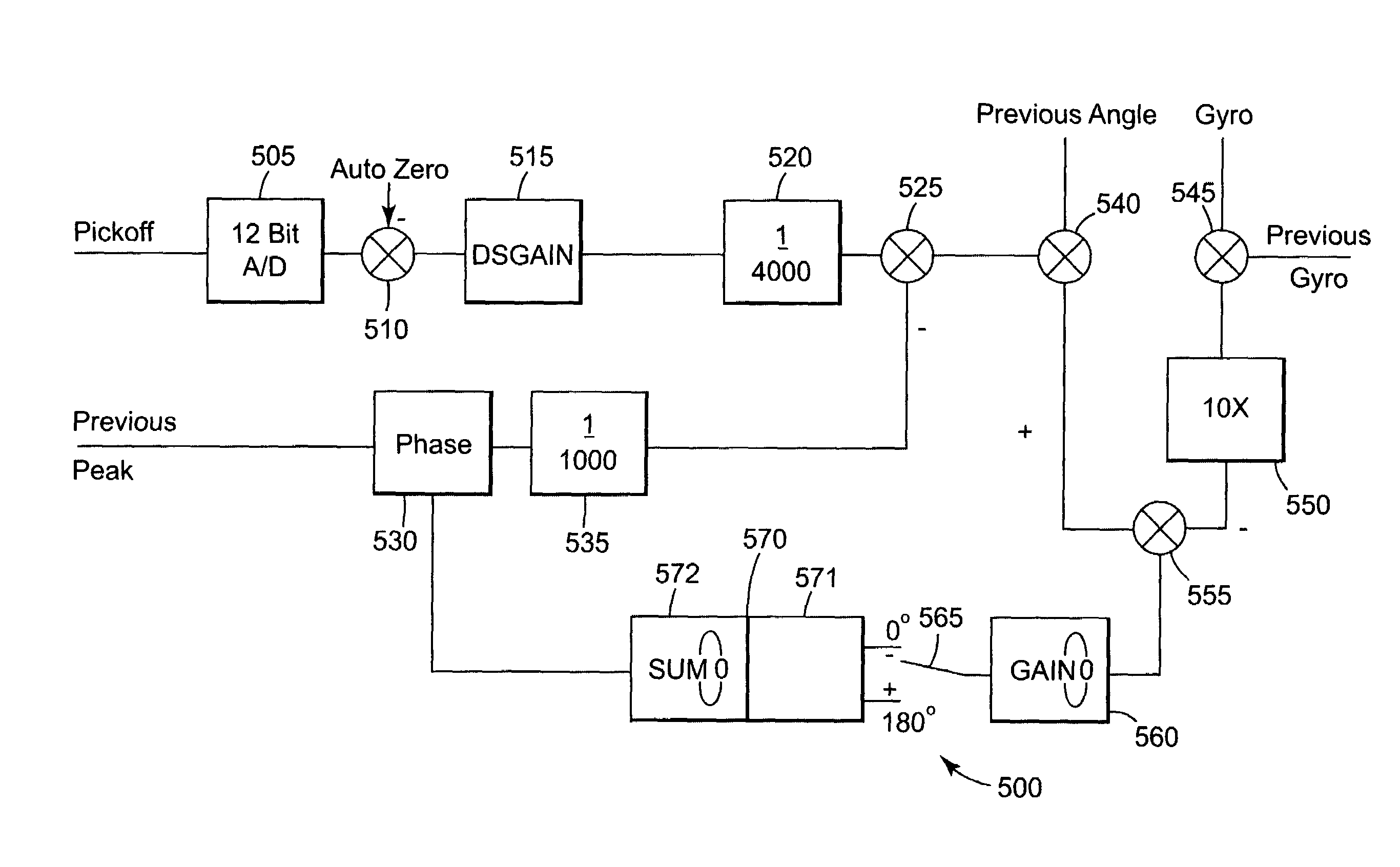
[0061]The present invention is a method and device for improving the quality of the dither pickoff signal for correction of a laser gyro. The dither pickoff signal is monitored at more points throughout the dither cycle. Instead of merely monitoring the dither pickoff signal at four points of the cycle (0°, 90°, 180° and 270°), the dither pickoff signal is sampled at eight points in the cycle, preferably at 0°, 45°, 90°, 135°, 180°, 225°, 270° and 315°. The pickoff signal at the additional times during the cycle provides additional information about the phase, DSGAIN and non-linearity values contained in the dither pickoff signal. This information is then used to calculate new values for k1 and k2 as dither pickoff signal correction factors. Use of the new values for k1 and k2 produce a dither pickoff signal with less error, which in turn allows for production of a more accurate gyro output signal.

Problems solved by technology

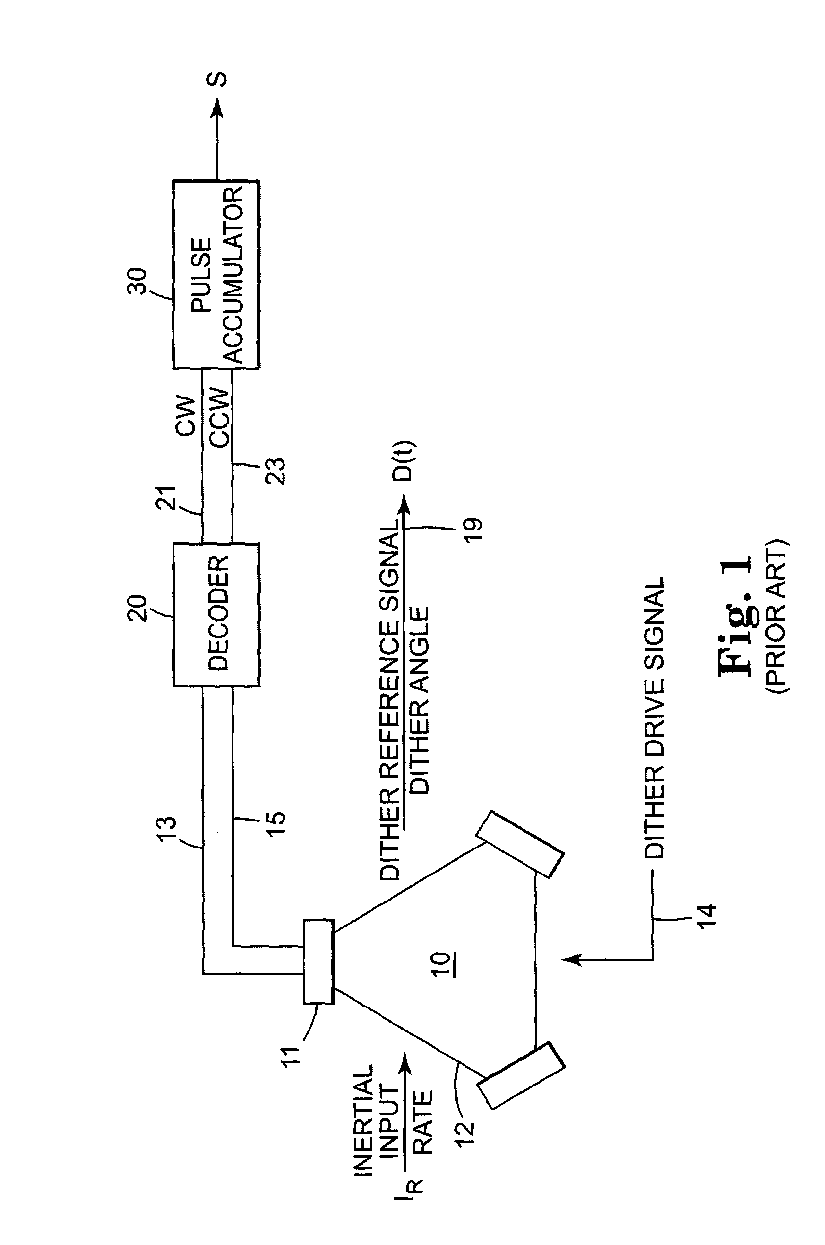
Associated with such sensors is an undesirable phenomenon called lock-in which has been recognized for some time in the prior art.
However, such techniques generate gain and phase shift disturbances that can affect the stability of any control loops or any readout signal processing systems.
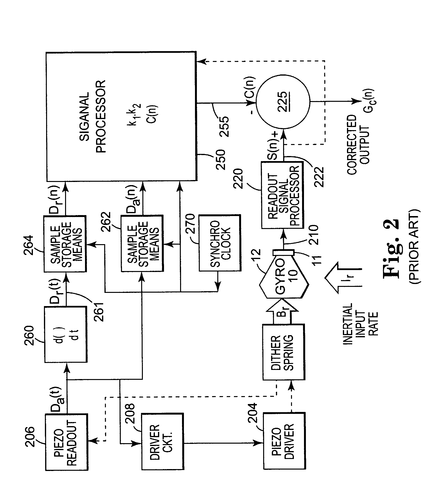
However, the piezo readout, that produces a dither pickoff signal, is not linear for all mechanical inputs.
The delay is due to propagation time for the dither input signal to drive the dither motor which in turn deforms the piezo sensors that create the dither pickoff signal.
While this produces good compensation coefficients for many purposes, it does not take into account the variations in the cubic non-linearities of the piezo sensor.
While this method of reducing error gives good control on these terms, it does not compensate for the variations in the cubic or square compensation terms in the non-linearity of the piezo-electric transducer.

Method used


Image

  • Dither stripper with non-linearity correction
  • Dither stripper with non-linearity correction
  • Dither stripper with non-linearity correction

Examples


Embodiment Construction

[0069]Referring now to FIG. 4 thereshown is a graph depicting the dither input 301A signal and the dither pickoff signal 302A. As shown, samples of the dither pickoff signal are taken at 0°, 45°, 90°, 135°, 180°, 225°, 270° and 315°. Equivalently, the measurements could be taken in the time domain of every one-eighth of a cycle of the dither input signal.

[0070]The reason for sampling the dither pickoff signal at these angles relates to the value of the phase error and offset at these specific dither input angles. At a dither input angle of 0° with the input signal equal to zero, the dither pickoff signal should be zero as well. By determining the dither pickoff signal value at this point, the phase error and square error term can be determined. This is true as well at the dither input angle of 180°

[0071]At a dither input angle of 45°, the dither pickoff signal contains elements related to the phase error and the offset and a cubic error term. This is true also at 135°, 225° and 315°...


PUM


Abstract

A method and apparatus for correction of laser gyro dither pickoff signals. Dither pickoff signals are sampled during the dither input signal cycle at points where error is more prevalent in the dither pickoff signal. The samples are then used to modify correction factors used in the calculation of a corrected dither pickoff signal.

Description

TECHNICAL FIELD[0001]This invention relates generally to a method and apparatus for removing the dither signal component from the inertial output of a laser gyro and more particularly to a method and apparatus for dither stripper gain correction.BACKGROUND OF THE INVENTION[0002]Ring laser angular rate sensors, also called laser gyros, are well known in the art. One example of a ring laser angular rate sensor is U.S. Pat. No. 4,751,718 issued to Hanse et al. Present day ring laser angular rate sensors include a thermally and mechanically stable laser block having a plurality of formed cavities for enclosing a gap. Mirrors are placed at the extremities of the cavities for reflecting laser beams and providing an optical closed-loop path.[0003]Associated with such sensors is an undesirable phenomenon called lock-in which has been recognized for some time in the prior art. During lock-in the counter-propagating laser beams tend to lock together to a common frequency. To avoid or reduce t...

Claims


Application Information

Patent Timeline
Patent Type & Authority Patents(United States)
IPC IPC(8): G01C19/68G01C19/66
CPCG01C19/664
Inventor KILLPATRICK, JOSEPH E.
Owner HONEYWELL INT INC
Why Eureka
Try Eureka