Dual “cheese wedge” silicon taper waveguide

a silicon taper waveguide and taper technology, applied in the field of tapered optical waveguides, can solve the problems of inability to achieve good fiber-silicon waveguide coupling and inability to reduce losses

Active Publication Date: 2006-08-08
INTEL CORP
View PDF5 Cites 37 Cited by
  • Summary
  • Abstract
  • Description
  • Claims
  • Application Information

AI Technical Summary

Problems solved by technology

Due to the high refractive index contrast of silicon waveguide systems, obtaining good fiber-silicon waveguide coupling is very challenging particularly for small silicon rib waveguides.
Since these small waveguides (1–2.5 μm) are often used for the high density silicon photonic integrated circuits and for better laser diode to silicon waveguide coupling, such losses may be unacceptable.

Method used


Image

  • Dual “cheese wedge” silicon taper waveguide
  • Dual “cheese wedge” silicon taper waveguide
  • Dual “cheese wedge” silicon taper waveguide

Examples


Embodiment Construction

[0016]In optical systems it may be challenging to efficiently couple light into and out of a chip. Particularly difficult may be the coupling of light from a standard optical fiber or external light source to a silicon waveguide owing to the differences in size, shape and refractive indices (n) between typical optical fibers and silicon waveguides. For example, a single-mode fiber core (n=1.5) usually has a diameter of 8 μm with a symmetric mode, while a silicon waveguide (n=3.5) is typically only a few micrometers in width with an asymmetric mode.

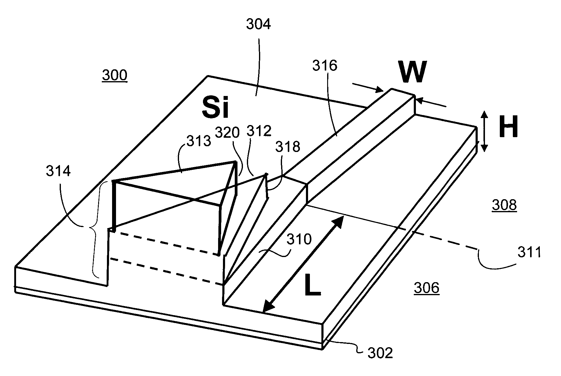
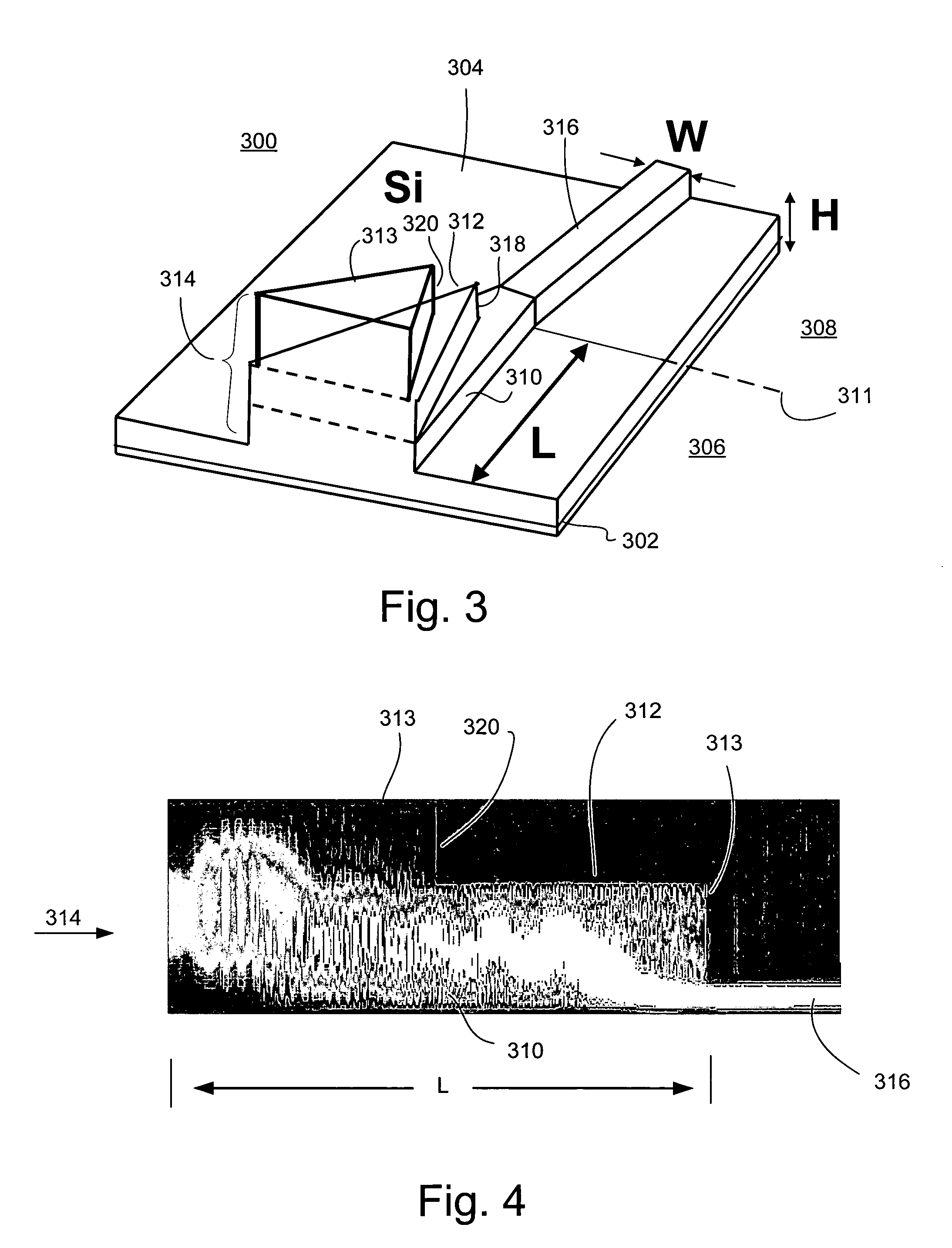
[0017]One method to address the aforementioned disparities may be to use a waveguide taper according to embodiments of the invention. Referring to FIG. 3, there is shown a plan view of a “dual cheese wedge” tapered waveguide 300. The waveguide 300 may be formed on a silicon-on-insulator (SOI) substrate comprising an insulator layer 302 and a silicon layer 304. The waveguide 300 generally comprises a tapered section 306 and an output wavegu...


PUM


Abstract

An optical device may include a fiber or waveguide that is intended to be coupled to another waveguide having a significantly larger / smaller cross-sectional size. As such, two wedge shaped waveguides may be positioned atop a tapered waveguide. The dual wedge design may allow for shorter taper lengths and smaller final waveguide cross section dimensions.

Description

FIELD OF THE INVENTION[0001]Embodiments of the present invention relate to waveguides, and more particularly, to tapered optical waveguides.BACKGROUND INFORMATION[0002]Efficient light coupling between an optical fiber and a silicon waveguide is highly desired for silicon based photonic device and circuit applications. Due to the high refractive index contrast of silicon waveguide systems, obtaining good fiber-silicon waveguide coupling is very challenging particularly for small silicon rib waveguides.[0003]Often is the case that an optical device includes a fiber or waveguide that is intended to be coupled to another waveguide having a significantly larger / smaller cross-sectional size. For example, a planar lightwave circuit (PLC) can have a waveguide on the order of four microns in height to be coupled to an optical fiber with a diameter of about ten microns. One way to couple a port of a relatively large waveguide to a port of a significantly smaller waveguide is by forming a tape...

Claims


Application Information

Patent Timeline
Patent Type & Authority Patents(United States)
IPC IPC(8): G02B6/12
CPCB82Y20/00G02B6/1228G02B6/1223
Inventor LIU, ANSHENG
Owner INTEL CORP
Why Eureka
Try Eureka