
Wireless channel setting method for mobile communication system and mobile communication control apparatus

a mobile communication system and control apparatus technology, applied in multiplex communication, power management, transmission monitoring, etc., can solve the problems of limited wireless capacity of cdma technology, inability to fully increase the transmission rate of individual channels, and long time for users to connect and start transmission, so as to reduce the connection time and increase the connection time

Inactive Publication Date: 2006-08-08
NTT DOCOMO INC
View PDF5 Cites 7 Cited by
  • Summary
  • Abstract
  • Description
  • Claims
  • Application Information

AI Technical Summary

Benefits of technology

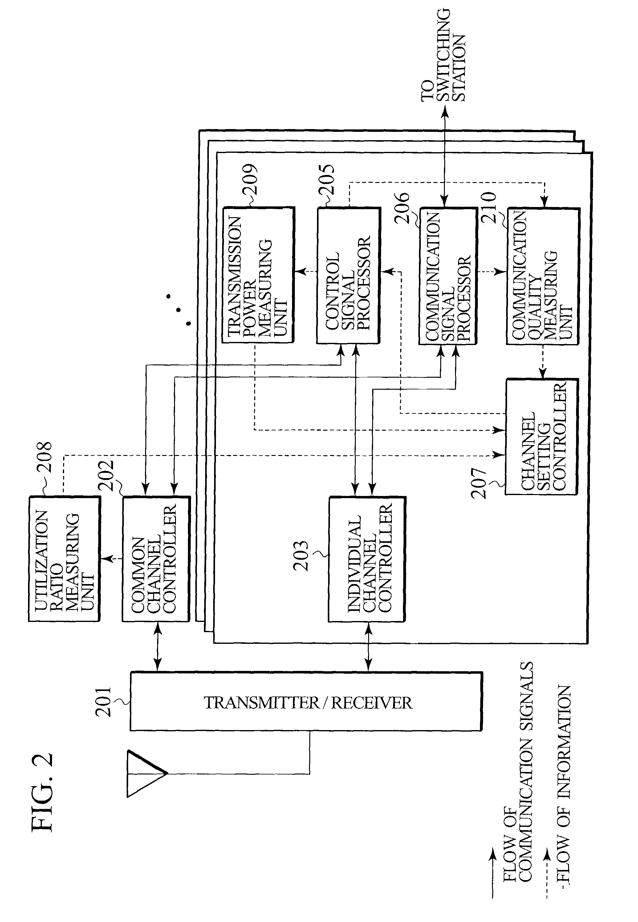
The present invention provides a mobile communication system with a wireless channel setting technique that reduces connection time and stabilizes communication quality. The technical effects of the invention include reducing interference and preventing an increase in connection time by setting individual channels for mobile stations near the edge of a cell. The wireless channel setting method involves comparing the transmission power value of a mobile station with a predetermined threshold value and switching between a common channel and an individual channel based on the transmission power value. The mobile communication system includes a transmitter / receiver, a control signal processor, a wireless channel setting controller, and a transmission power measuring unit.

Problems solved by technology

Since the wireless capacity with the CDMA technology is limited by the level of the interference from other mobile stations located within the same cell, the minimum required power must be employed by all mobile stations in the same cell when communicating with each other in order to reduce interference.
However, according to a system such as the conventional mobile communication system, whereby an individual channel for control use and an individual channel for communication use are sequentially set from the common channel, it takes a long time for a user to connect and start transmission and to be capable of voice or data transmission, which has been problem.
On the other hand, since the individual channel for control use is employed only by a pertinent mobile station, the transmission rate for the individual channel can not be thoroughly increased while taking the wireless and hardware resources into account if these are in proportion to the transmission rate.
However, according to this countermeasure, regarding the state when the common channel is used, because of the system configuration, fast transmission power control is impossible, and depending on the conditions at the mobile station such as the current location thereof and the utilization thereof, the system capacity and the communication quality obtained may be unsatisfactory, compared with the state wherein an individual channel is used.
Further, since the transmission rate for the common channel is higher and the peak transmission power is greater compared with those for an individual channel, the uplink and downlink paths through the common channel tend to act as interference sources for other mobile stations, especially when the pertinent mobile station is located near the edge of a cell.
Furthermore, when the transmission power reaches the upper limit, a satisfactory communication quality is apt to not be obtained.
And in addition, when multiple mobile stations are connected to the common channel, a delay in the uplink random access and a delay in the downlink transmission waiting may occur due to a contention control, and the connection time may be further extended.

Method used


Image

  • Wireless channel setting method for mobile communication system and mobile communication control apparatus
  • Wireless channel setting method for mobile communication system and mobile communication control apparatus
  • Wireless channel setting method for mobile communication system and mobile communication control apparatus

Examples


Embodiment Construction

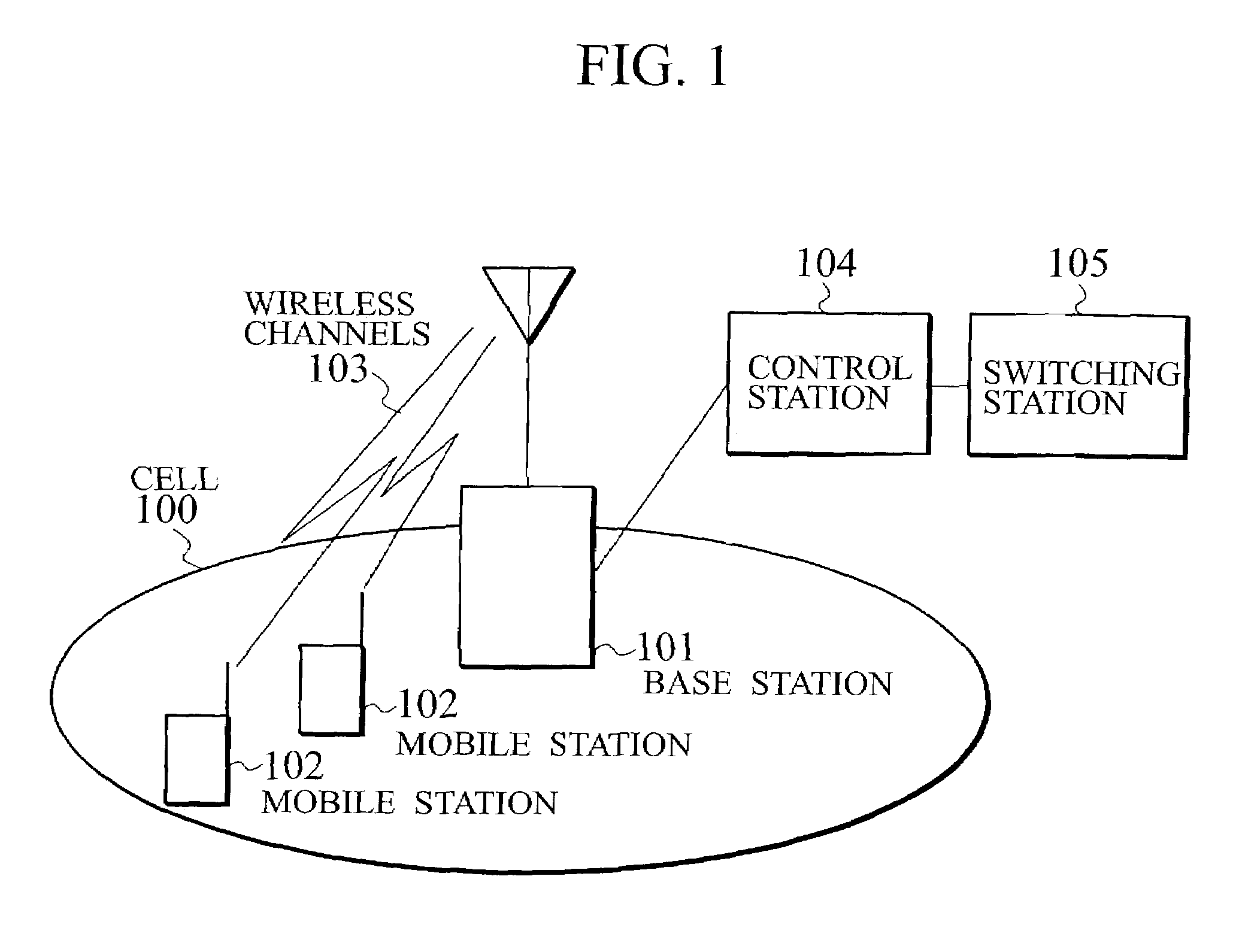
[0038]The preferred embodiment of the present invention will now be described in detail. The configuration of a mobile communication system according to one embodiment of the present invention is shown in FIG. 1. The mobile communication system includes a wireless base station 101, one or a plurality of mobile stations 102, a control station 104 and a mobile switching station 105. The wireless base station 101 performs communication with the mobile stations 102. The mobile stations 102 are located in a wireless zone (cell) 100 covered by the wireless base station 101. The control station 104 is connected to the wireless base station 101 and controls the wireless base station 101 and the mobile stations 102. The mobile switching station 105 is connected to the control station 104.

[0039]Wireless channels 103 are set up between the wireless base station 101 and the mobile stations 102 for wireless communication. The wireless channels 103 include a common channel over which all of the m...


PUM


Abstract

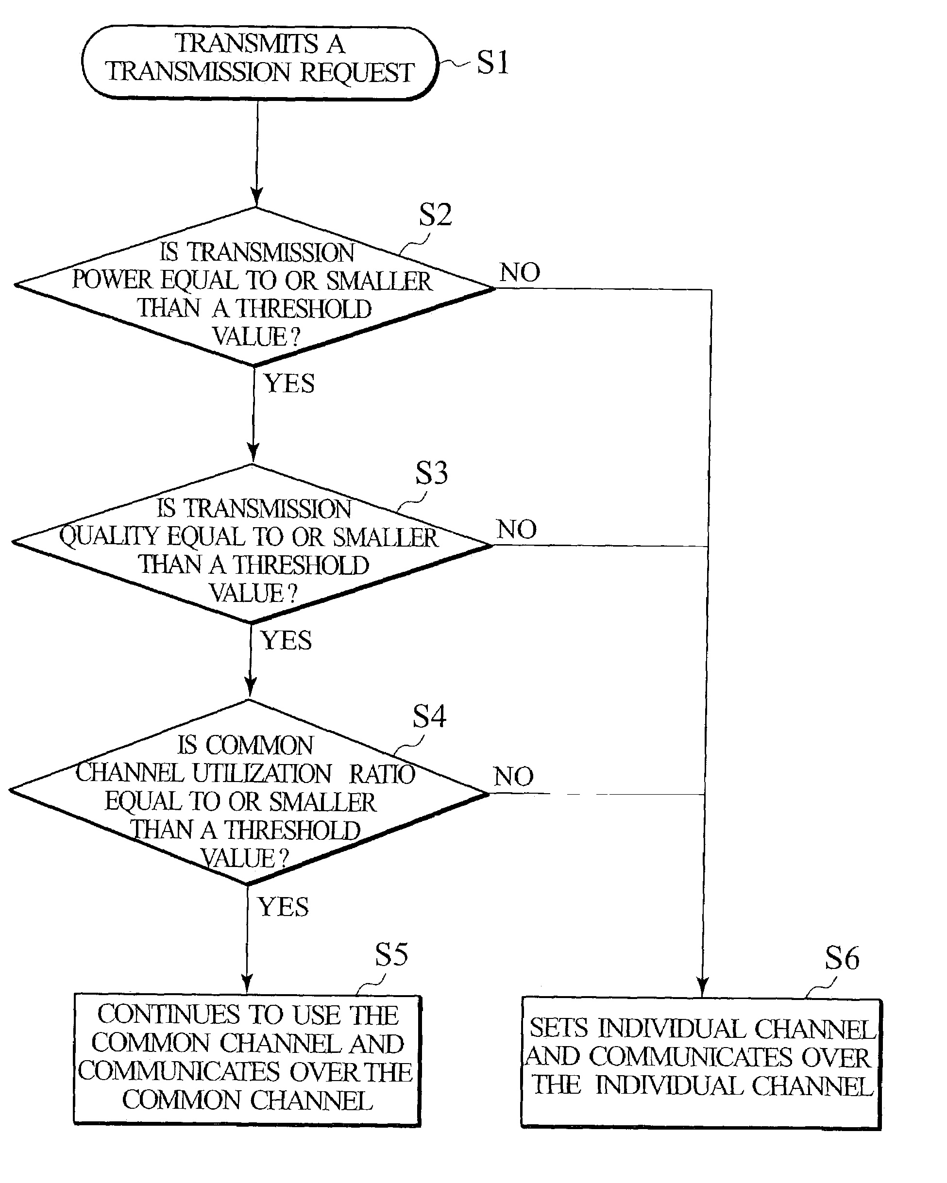
Disclosed is a mobile communication system whereby, to reduce the connection time, a mobile station closely located to a base wireless station is permitted to continue to use a common channel for exchanging signals, and to suppress an increase in interference, an individual channel is set for a mobile station located near the edge of a cell, and to obtain a stabilized communication quality and to prevent an increase in the connection time, the probability that the transmission power will reach an upper limit is reduced. When communication between a mobile station and a wireless base station is started, the wireless base station measures the transmission power and the communication quality in the communication with the mobile station and the utilization ratio for a common channel, and compares the obtained values with predetermined threshold values. When the obtained values are lower than the threshold values, the wireless base station continues to use the common channel for signal transmission / reception. On the other hand, when the obtained values exceed the threshold values, the wireless base station sets an individual channel and sets a wireless channel so as to be capable of the continued use of the individual channel for the exchange of signals.

Description

CROSS-REFERENCE TO RELATED APPLICATION[0001]This application is based upon and claims the benefit of priority from the prior Japanese Patent Application No. 2002-183525, filed on Jun. 24, 2002. The entire contents of which are incorporated herein by reference.BACKGROUND OF THE INVENTION[0002]1. Field of the Invention[0003]The present invention relates to a wireless channel setting method for a mobile communication system and a mobile communication control apparatus.[0004]2. Related Background Art[0005]A mobile communication system, called “FOMA” (product name) system, that employs CDMA (Code Division Multiple Access) is well known as an IMT-2000 wireless access technique. For this mobile communication system, the following method is employed to set up a wireless channel between a mobile station and a wireless base station.[0006]Since the wireless capacity with the CDMA technology is limited by the level of the interference from other mobile stations located within the same cell, the...

Claims


Application Information

Patent Timeline
Patent Type & Authority Patents(United States)
IPC IPC(8): H04B7/00H04B1/707H04B7/26H04J13/00H04W16/02H04W52/04H04W64/00H04W72/04H04W72/06H04W76/02
CPCH04W36/06H04W24/00H04W24/10
Inventor KATO, YASUHIRONAKAMURA, TAKEHIROONOE, SEIZOMAEBARA, AKIHIROOHTO, YUTAKAUEDA, SHINJI
Owner NTT DOCOMO INC
Learn More