Eureka AIR delivers breakthrough ideas for toughest innovation challenges, trusted by R&D personnel around the world.

Method and system of exciting a driving vibration in a vibrator

Active Publication Date: 2006-08-15
SEIKO EPSON CORP
View PDF12 Cites 10 Cited by
  • Summary
  • Abstract
  • Description
  • Claims
  • Application Information

AI Technical Summary

Benefits of technology

[0008]The assignee filed a Japanese patent application 2001-207264A (Japanese patent publication 2003-21518A) and disclosed a method of exciting a driving vibration in a vibrator for measurement and to detect a physical value applied on the vibrator based on a detection signal obtained from the vibrator. In the publication, it is disclosed a method of activating a vibrator for measurement for reducing a rise time until the vibration of the vibrator is stabilized.
[0010]An object of the present invention is to reduce a rise time required for stabilizing the vibration state of a vibrator and to reduce the scale of a circuit needed for the activation of a driving vibration in exciting the driving vibration in the vibrator.
[0014]According to the present invention of exciting a driving vibration in a vibrator for outputting a detection signal generated based on the driving vibration and a physical value and for measuring the physical value based on the detection signal, a rise time needed for stabilizing the vibration state of the vibrator can be reduced. Moreover, it is not required an oscillator dedicated to add an addition signal to a self-oscillating circuit. In addition to this, a signal from the CR oscillation circuit or ring oscillator is automatically separated from the self-oscillating circuit when the level of the driving signal is elevated, so that a switching circuit is not required. It is thus possible to reduce the scale of the circuit for self-oscillation, to lower the cost and to reduce the dimension of the circuit.

Problems solved by technology

If a gyroscope is activated at the time when a vehicle is started, it takes a long time until the operation of the vibratory gyroscope is stabilized after the activation.
It is impossible to confirm the direction and position of the vehicle until the operation of the gyroscope is stabilized.
Such long waiting time makes the application of the gyroscope to the position control of the vehicle difficult.
Such activation circuit is inevitably of a large scale.
The scale of the activation circuit may be large, the cost tends to be high and the dimension of the circuit tends to be large.
The response is not necessarily good when a driving vibration of rectangular wave is applied.

Method used


Image

  • Method and system of exciting a driving vibration in a vibrator
  • Method and system of exciting a driving vibration in a vibrator
  • Method and system of exciting a driving vibration in a vibrator

Examples


examples

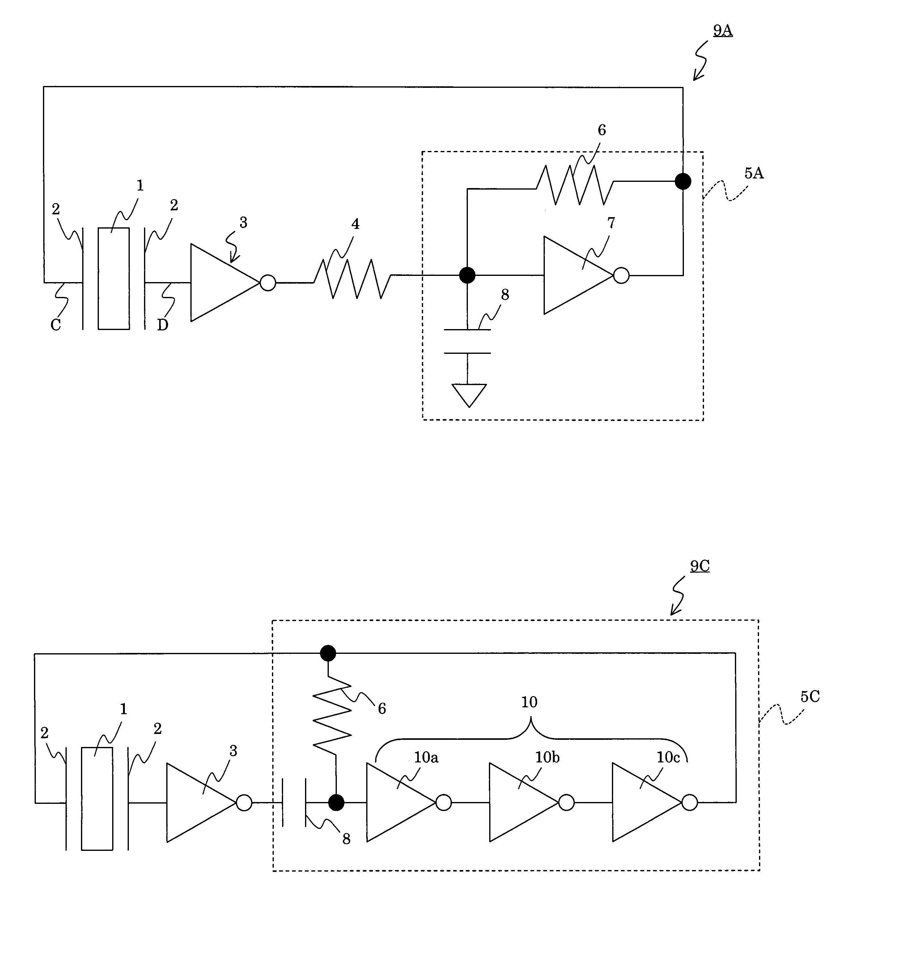
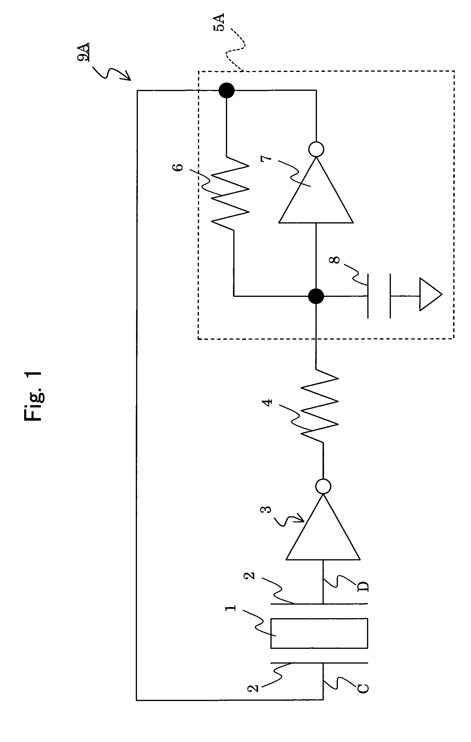
[0050]An experiment for exciting a driving vibration is performed applying a circuit described above referring to FIGS. 8 and 9. A vibrator described in Japanese patent publication 11-281372A was used. The vibrator had two driving vibration pieces 1a, and two detection vibration pieces 1b and 1c vibrating independently from the driving vibration pieces. Noise in a frequency range of 100 to 500 kHz was generated from the activation circuit, and then input into the oscillation loop to activate self-oscillation. The delay time of the comparator was 1.0 μs (500 kHz), the amplitude of output was 2Vp-p, and the width of dead zone voltage was 5 mV. The resistance of the resistor 6 was 10 MΩ, and the capacity of the condenser 8 was 10 pF (1 MHz). A time period required for stabilizing the oscillation of the driving signal was about 0.160 seconds. The amplitude of the driving signal was 1.1 V and the frequency was 44.1 kHz.

[0051]As described above, according to the present invention, a rise ...


PUM


Abstract

An object of the present invention is to reduce a rise time required for stabilizing the vibration state of a vibrator and the scale of a circuit needed for the activation of a driving vibration in exciting the driving vibration in the vibrator. A driving vibration is excited in a vibrator 1 for outputting a detection signal generated based on the driving vibration and a physical value, and the physical value is measured based on the detection signal. The driving vibration is excited using a circuit 9A for self-excited vibration having a CR oscillator 5A to generate an oscillation loop together with the vibrator 1. An activating signal of rectangular wave is applied on the vibrator 1 using the CR oscillator 5A to start the driving vibration in the vibrator 1.

Description

[0001]This application claims the benefit of Japanese Patent Application P2003-77155 filed on Mar. 20, 2003, the entirety of which is incorporated by reference.BACKGROUND OF THE INVENTION[0002]1. Field of the Invention[0003]The present invention provides a method and system for exciting a driving vibration in a vibrator.[0004]2. Related Art Statement[0005]It has been studied to use a vibratory gyroscope as a turning angular rate sensor employed in a vehicle control system of an automobile body based on a vehicle turning rate feedback system. Such a system detects the direction of a steering wheel itself by a turning angle of the steering wheel. Simultaneously, the turning rate of the car vehicle is detected by the vibratory gyroscope. The system finds a difference by comparing the direction of the steering wheel with the actual body turning velocity, and attains a stable vehicle control by correcting a wheel torque and a steering angle on the basis of this difference.[0006]Japanese ...

Claims


Application Information

Patent Timeline
IPC IPC(8): G01P15/10G01C19/00G01C19/56G01C19/5776G01D5/244
CPCG01C19/56
Inventor YOKOI, SHOJIKOBAYASHI, YOSHIHIRO
Owner SEIKO EPSON CORP
Why Eureka
Eureka Blog
Learn More