Diversity receiver and gain adjusting method therefor

Inactive Publication Date: 2009-01-08
NEC CORP
View PDF1 Cites 0 Cited by
  • Summary
  • Abstract
  • Description
  • Claims
  • Application Information

AI Technical Summary

Benefits of technology

[0026]Thus, a diversity receiver and a gain adjusting method therefor of the present invention can restrain deterioration of the S/N ratio to produce effects resulting from the employment of the diversity reception scheme, as compared with the configuration illustrated in FIG.

Problems solved by technology

This results in approximately 50 dB of difference (dynamic range) between a maximal non-distortion input level available to A/D conversion and the quantization noise.
When the diversity reception scheme is applied to the W-CDMA based radio communication system, problems as described below will arise if a

Method used


Image

  • Diversity receiver and gain adjusting method therefor
  • Diversity receiver and gain adjusting method therefor
  • Diversity receiver and gain adjusting method therefor

Examples


Example

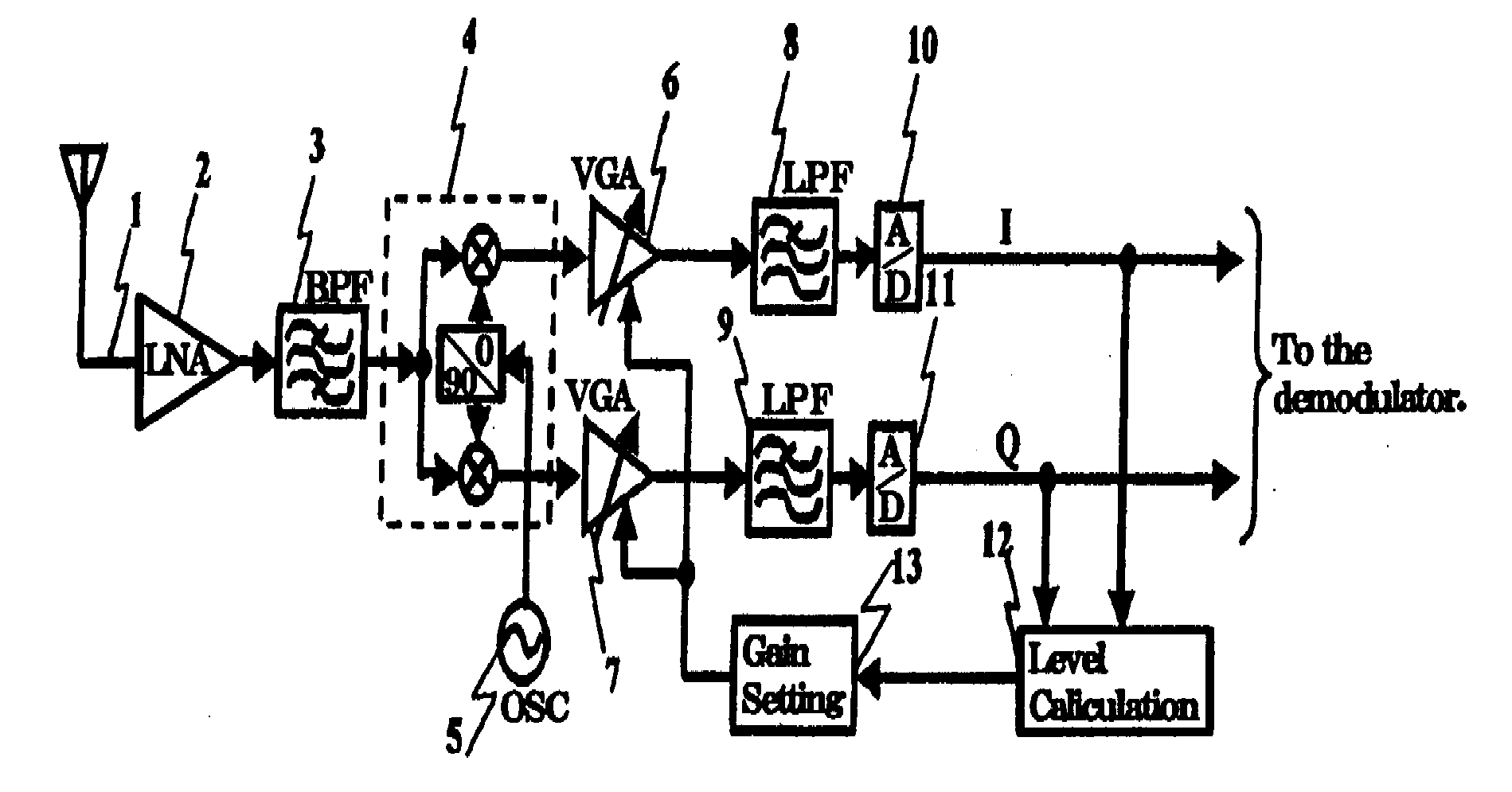
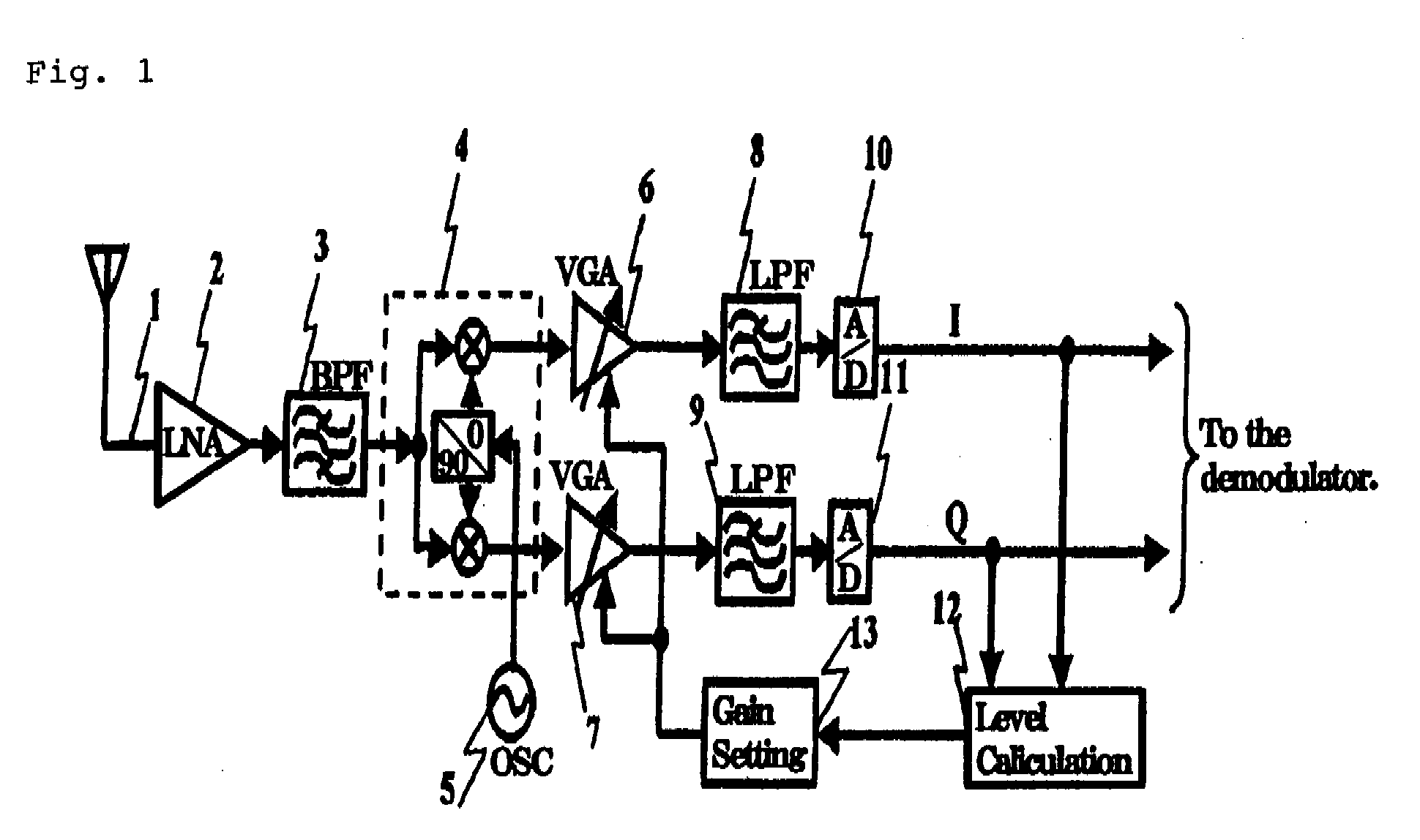
[0033]FIG. 4 is a block diagram illustrating an exemplary configuration of a diversity receiver according to the present invention, and FIG. 5 is a graph showing the output level of each branch after a gain adjustment of the diversity receiver illustrated in FIG. 4. In FIG. 4, components similar to those in the conventional receiver illustrated in FIG. 2 are designated similar reference numerals to those in FIG. 2.

[0034]The diversity receiver of the present invention is suitable for application to a radio communication system having a wide dynamic range of reception levels, like a W-CDMA scheme, which is required to finely adjust the gains of receivers, in order to carry out optimal and stable receptions.

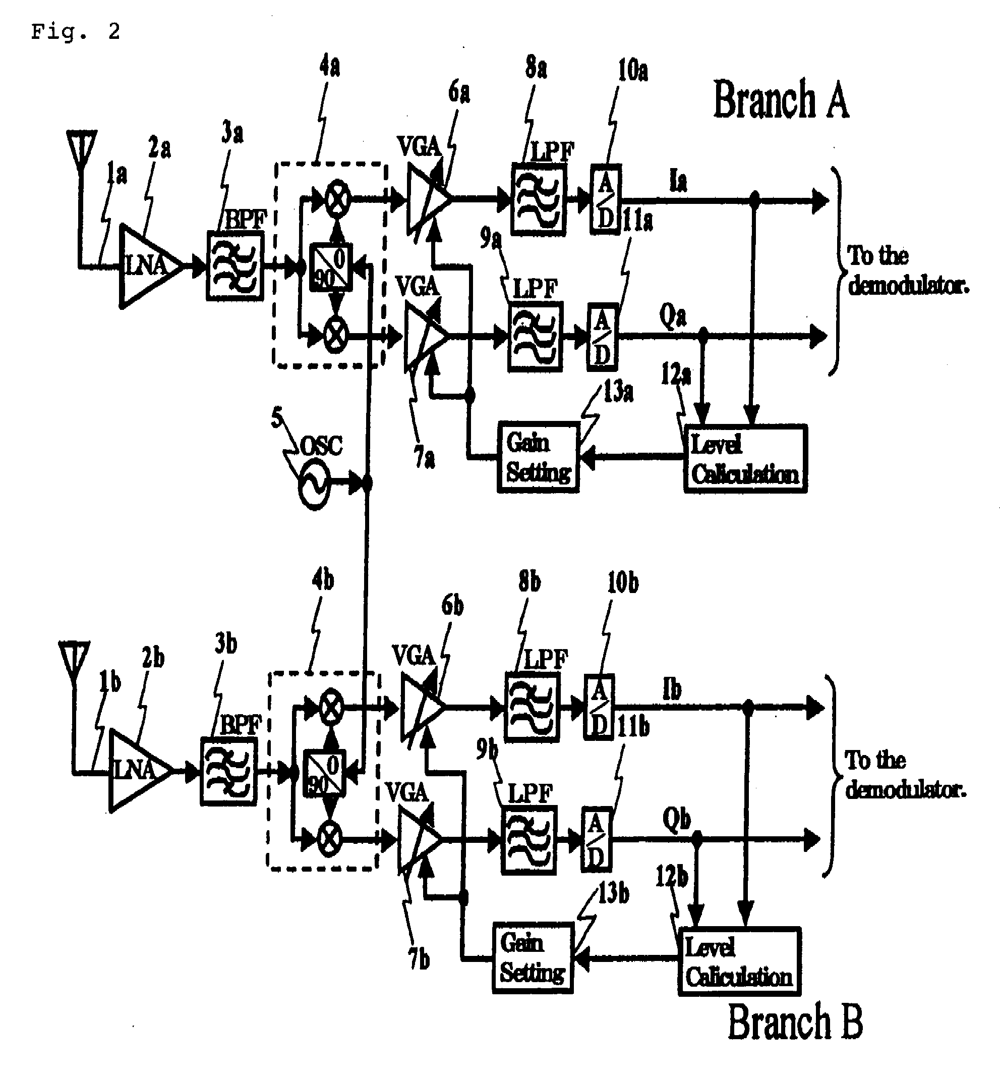
[0035]As illustrated in FIG. 4, the receiver of this embodiment is a diversity receiver which comprises branches (Branches) A, B, and local oscillator 5 and gain setting circuit 13 shared by branches A, B.

[0036]The diversity receiver of this embodiment differs in configuration from ...


PUM


Abstract

Reception levels are measured in respective branches to compare the results of the measurements with one another to select the result of the measurement of a maximum reception level which is the highest reception level. The gains of variable gain amplifiers (6. 7) of all the branches including variable gain amplifiers (6, 7) included in a branch corresponding to the maximum reception level are adjusted to the same value such that output levels of the variable gain amplifiers (6, 7) are set to a preset target level.

Description

TECHNICAL FIELD[0001]The present invention relates to a diversity receiver and a gain adjusting method therefor which are suitable for application to a W-CDMA (Wideband Code Division Multiple Access) based radio communication system.BACKGROUND ART[0002]Referring to FIG. 1, a description will be first given of the configuration of a conventional receiver, used in a W-CDMA based radio communication system, which does not employ a diversity reception scheme. It should be noted that the receiver illustrated in FIG. 1 has a configuration which is predicated on a direct conversion scheme which directly converts a received radio frequency signal to a baseband signal. Direct conversion based receivers are described in detail, for example, in Japanese Patent No. 3329264, Japanese Patent No. 3479835, and the like.[0003]As illustrated in FIG. 1, in the conventional receiver, a signal received by antenna 1 is amplified by LNA (low-noise amplifier) 2. The signal delivered from LNA 2 is converted...

Claims


Application Information

Patent Timeline
IPC IPC(8): H04B10/06H04B17/40H04B1/30H04B7/08H04W88/02
CPCH04B7/0857
Inventor ICHIHARA, MASAKI
Owner NEC CORP
Why Eureka
Try Eureka