Ophthalmic lens manufacturing system

a manufacturing system and lens technology, applied in the direction of grinding feeders, grinding drives, manufacturing tools, etc., can solve the problems of inability to automatically adjust themselves depending, deficient current manufacturing cells in several respects, and requiring manual labor to perform or assist with the edging process

Inactive Publication Date: 2006-08-15
AIT IND +1
View PDF68 Cites 22 Cited by
  • Summary
  • Abstract
  • Description
  • Claims
  • Application Information

AI Technical Summary

Problems solved by technology

The current manufacturing cells are deficient in several respects.
First, while some robotic arms use suction cups connected to a vacuum source to lift the lenses from the tray, these suction cups are not of a compliant nature and cannot automatically adjust themselves depending on the thickness and / or curvature of a particular lens.
Because of the dimensional limitations of the interior of an edging machine, the lack of a compliant pickup mechanism on a robotic arm prevents thicker lenses from being used with a robotic lens manufacturing cell, thus requiring manual labor to perform or assist with the edging process.
Also, not having a complaint gripper mechanism increases the likelihood that a lens will be dropped by the robotic arm, which leads to lowered productivity.
Second, a typical manufacturing cell will have a robotic arm placed in the center of a plurality of lens edging machines.
However, if a lens becomes jammed within an edger, or if an edger requires maintenance, the inward-facing nature of the edging machines makes un-jamming the machine or performing maintenance on the machine a burdensome and time-consuming task.
Third, because individual edging machines need to be replaced or serviced from time to time, it is necessary to remove edgers from the manufacturing cell periodically.
However, heretofore, the removal of an edger has been a complicated task.
Fourth, due to the speed in which the robotic arm in an ophthalmic lens manufacturing cell moves, it is somewhat common that the lenses contained in the tray will periodically move out of their preset locations within the tray, which prevents the robotic arm from subsequently picking up the lens and placing it in an edging machine.
This arrangement is not very efficient because allocating time for communication of a robot directly to the lab server which, in turn, must communicate the complete data regarding the particular ophthalmic lens to be manufactured (or edged) to each individual edger results in a greater total time of communication, thus resulting in lower throughput (i.e., capacity) of the manufacturing cell.

Method used


Image

  • Ophthalmic lens manufacturing system
  • Ophthalmic lens manufacturing system
  • Ophthalmic lens manufacturing system

Examples


Embodiment Construction

[0022]While the present invention is capable of embodiment in various forms, there is shown in the drawings and will be hereinafter described a presently preferred embodiment with the understanding that the present disclosure is to be considered as an exemplification of the invention, and is not intended to limit the invention to the specific embodiment illustrated.

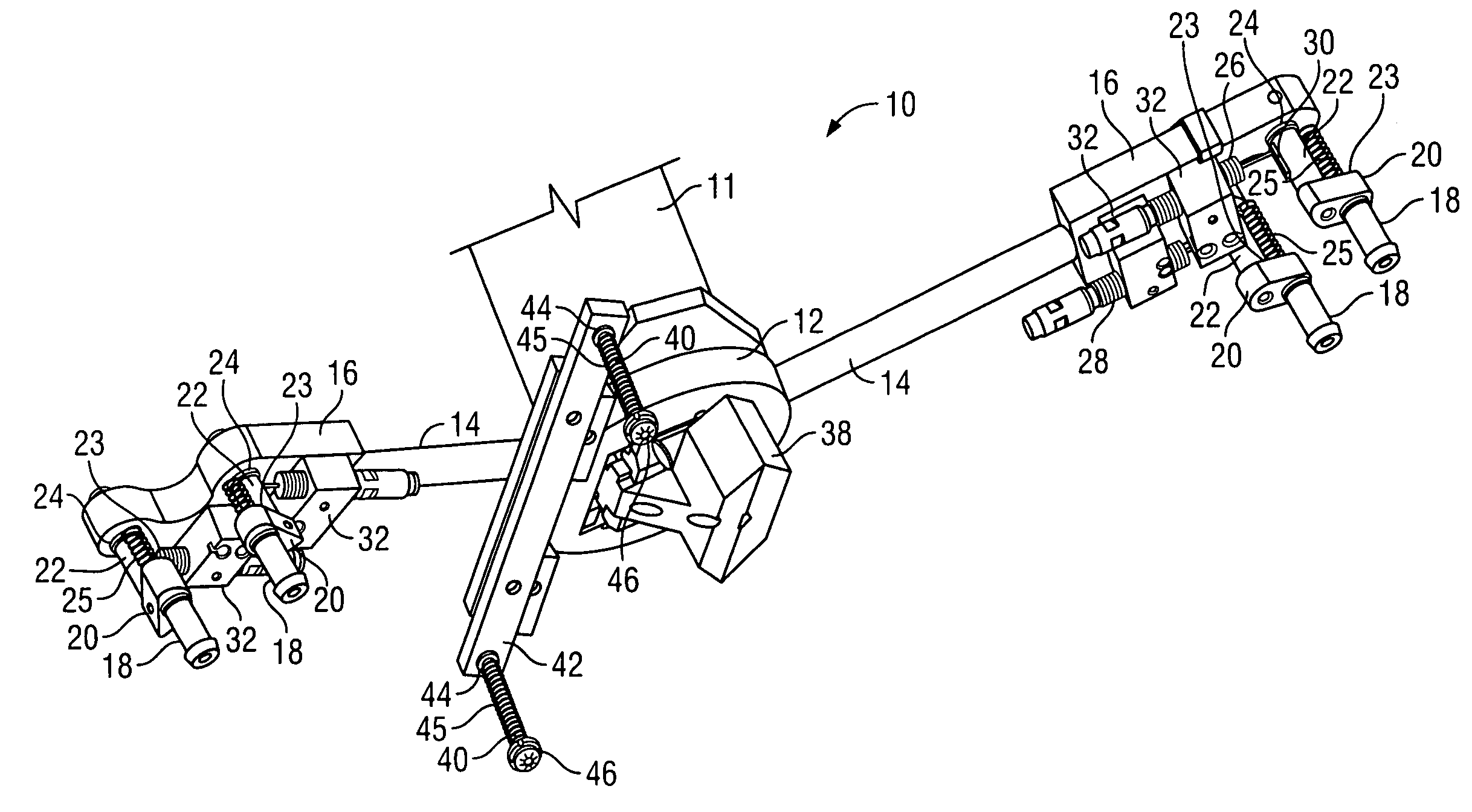
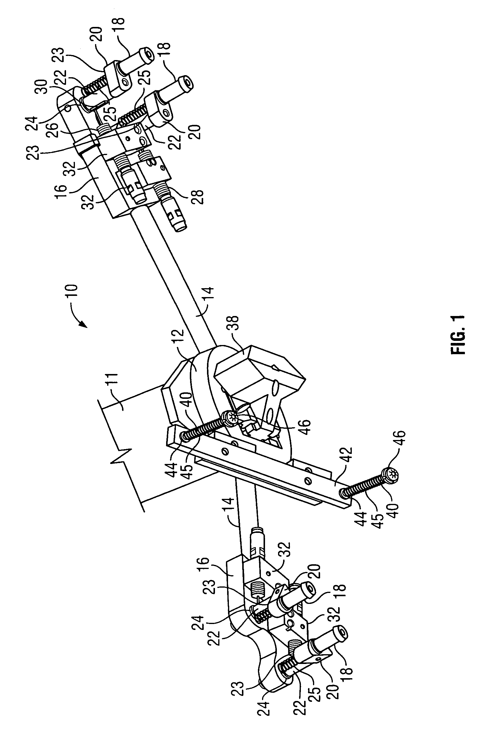
[0023]With reference to FIG. 1, one embodiment of the present invention contains a gripper tool 10, which is attached to the working end of a commercially available robotic arm 11. It is preferred that one embodiment of the present invention be used with a six axis robotic arm to allow for greater versatility, but those with skill in the art will recognize that robots having a lesser or greater number of axes can be used in the practice of the present invention. A six axis robotic arm which can be used with one embodiment of the present invention is a robotic arm manufactured by Adept (model number A600).

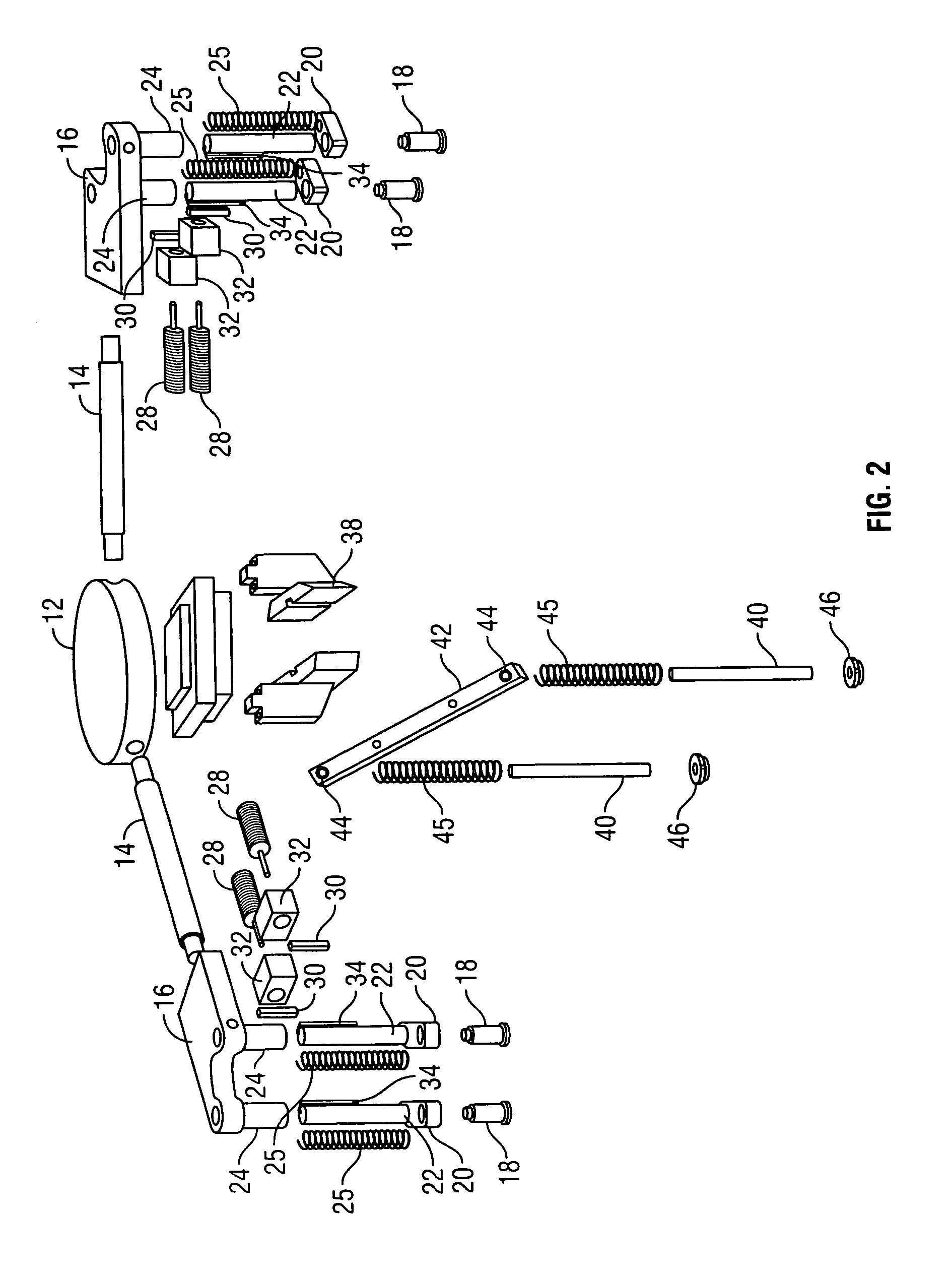
[0024]The gripper...


PUM

PropertyMeasurementUnit
resilientaaaaaaaaaa
pressureaaaaaaaaaa
thicknessaaaaaaaaaa

Abstract

A tool for gripping ophthalmic lenses including a vacuum gripper, a shaft associated with said vacuum gripper, the shaft having two ends and being slidably attached at one end thereof to a support structure, a resilient member which biases the vacuum gripper in a direction away from said support structure and a locking member which locks the shaft in a desired position during a lens gripping operation.Another embodiment of the present invention includes a lens hold down mechanism for holding lenses in a lens tray.Another embodiment of the present invention includes an electronic communications scheme for a robotic manufacturing operation.Another embodiment of the present invention includes an ophthalmic lens manufacturing cell layout wherein ophthalmic edging machines have an opening that faces away from a robotic arm.Another embodiment of the present invention includes an arrangement for holding an ophthalmic edging machine within an ophthalmic manufacturing cell.

Description

FIELD OF INVENTION[0001]This invention relates generally to an ophthalmic lens manufacturing system, and more particularly to a lens manufacturing system wherein one or more robotic arms communicates with a plurality of lens edgers in a robotic manufacturing cell.BACKGROUND OF INVENTION[0002]Modern ophthalmic lens processing systems comprise three main components: a robotic arm, a plurality of edging machines, and a host lab server to control the lens manufacturing operation. The robotic arm, the edging machines and the host lab server form what is known as a ophthalmic lens manufacturing “cell”. Typically, lenses arrive at the cell in trays which hold the lenses in a position such that their convex side is facing up. These trays are picked up by a robotic arm and brought to an edging machine, whereby the lenses are removed from the tray with the robotic arm and placed in the edging machine. When the edging operation is complete, the lenses are placed back in the tray and returned t...

Claims


Application Information

Patent Timeline
Patent Type & Authority Patents(United States)
IPC IPC(8): B24B51/00B24B9/14B24B27/00B24B41/00B25J15/00B25J15/06
CPCB24B9/14B24B27/0023B25J15/0616B25J15/0052B24B41/005
Inventor VULICH, MATTHEWPATEL, BHAVENALBERT, SANTIAGO
Owner AIT IND
Why Eureka
Try Eureka