
Perpendicular magnetic recording medium

Inactive Publication Date: 2006-08-15
WD MEDIA SINGAPORE PTE
View PDF12 Cites 69 Cited by
  • Summary
  • Abstract
  • Description
  • Claims
  • Application Information

AI Technical Summary

Benefits of technology

[0012]It is therefore an object of the present invention to provide a perpendicular magnetic recording medium having a reduced effect of the demagnetizing field caused by a magnetic poles generated on a perpendicular magnetization film surface and having a preferable medium noise characteristic in a low recording density region.
[0019]In the perpendicular magnetic recording medium according to the present invention, the perpendicular magnetization film on its upper surface or lower surface a high perpendicular orientation film having a higher perpendicular orientation than that of the perpendicular magnetization film. Accordingly, it is possible to significantly suppress generation of a reversed magnetic domain in the vicinity of the surface of the perpendicular magnetization film.
[0021]On the other hand, when the high perpendicular orientation film is made from a SmCo alloy (i.e., a material other than the CoCr alloy), it is preferable that the high perpendicular orientation film have a perpendicular magnetic anisotropic energy Ku greater than that of the perpendicular magnetization film. This enables to reduce generation of reversed magnetic domain in the vicinity of the surface of the perpendicular magnetization film.

Problems solved by technology

However, in order to realize a high recording density in the conventional longitudinal direction recording method, there are various problems.
For example, if the recording bit is made smaller, there arises a problem of thermal fluctuation of recording magnetization and a problem of high coercive force which may exceed the recording capability of the recording head.
However, in such a conventional perpendicular magnetic recording medium, there has been a problem that medium noise characteristic is very bad in a low recording density region.
This has been the main cause to deteriorate the medium noise characteristic in the low recording density region.
This medium noise increase in the low recording density region becomes a big trouble when forming a high-density information recording apparatus.
However, in this two-layered perpendicular magnetic recording medium, if a perpendicular magnetization film is provided on a soft magnetic layer such as NiFe (Permalloy), there arises a problem that the soft magnetic layer generates a spike-shaped noise, disabling to obtain a preferable medium S / N ratio.
This results in concentration of the magnetic flux in a magnetic head and losing of recording signals.
That is, the perpendicular magnetic recording medium of the two-layered film configuration can reduce the effect of the demagnetizing field caused by the magnetic poles generated on the medium surface, but this cannot be a solution for medium noise reduction.

Method used


Image

  • Perpendicular magnetic recording medium
  • Perpendicular magnetic recording medium
  • Perpendicular magnetic recording medium

Examples


example 1

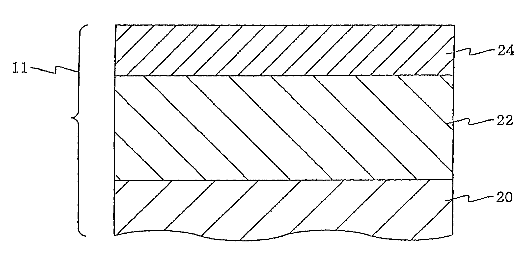
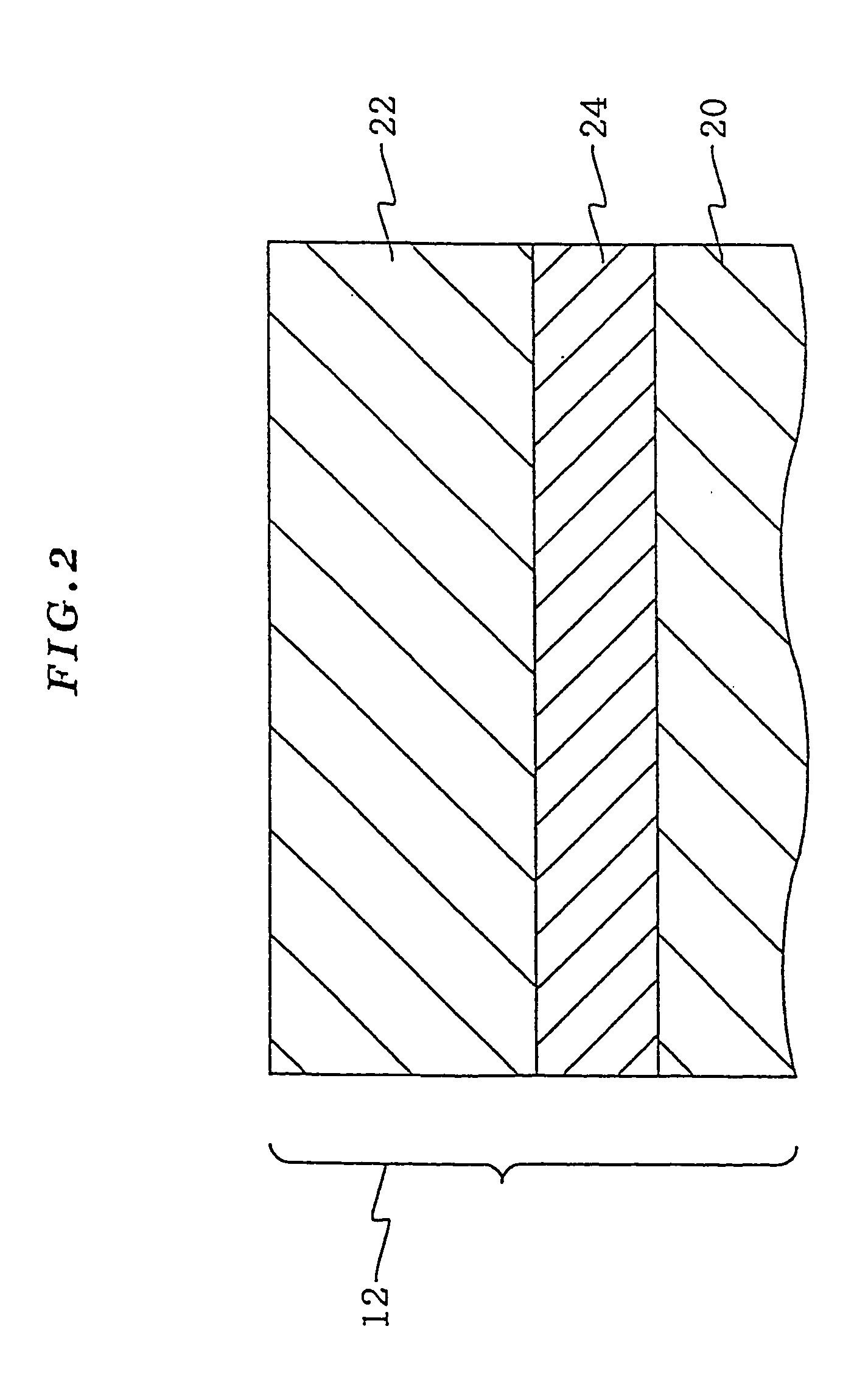
[0181]Using a 6-inch Co80Cr17Ta3 (%) target for sputtering, a perpendicular magnetization film Co80Cr17Ta3 was formed to have a thickness of 100 nm on a 2.5-inch substrate at 400 degrees centigrade. The film formation conditions were as follows: initial vacuum degree 5×10⁻⁷ [mTorr]; electric power 0.5 [kw]; argon gas pressure 4 [mTorr]; film formation speed 3 [nm / sec].

[0182]After this, the film was covered by the high perpendicular orientation film of 5 to 55 [nm] thickness formed by using: a Co74Cr22Pt2TaLa target, a Co75Cr21Pt2TaLa target, a Co76Cr20Pt2TaLa target, a Co77Cr19Pt2TaLa target, and a Co78Cr18Pt2TaLa target.

[0183]After this, a C (carbon) protection film 10 [nm] was formed to cover the high perpendicular orientation film.

[0184]The medium having the high perpendicular orientation film of Co76Cr20Pt2TaLa of 50 [nm] thickness will be referred to as medium AAA2 of the present invention. On the other hand, the medium having only the perpendicular magnetization film Co80Cr17T...

example 2

[0193]Media of Example 2 were prepared in the same way as Example 1 except for that the CoxCr96−xPt2TaLa (74≦x≦78) target was replaced by CoxCr96−xPt2TaLu (74≦x≦78) target. The medium examples made from Co76Cr20Pt2TaLu film having a film thickness of 50 [nm] will be referred to as medium BBB2 of the present invention. Note that we also prepared media having the Co80Cr17Ta3 film and the Co76Cr20Pt2TaLu film in the reversed order, i.e., firstly Co76Cr20Pt2TaLu film was formed on the substrate, and then the Co80Cr17Ta3 film was formed thereon.

[0194]The perpendicular magnetic anisotropic energy Ku of the following six films were measured using a torque magnetometer; and saturation magnetization Ms of these six films were measured using a sample vibration type magnetometer (VSM): a Co74Cr22Pt2TaLu film, a Co75Cr21Pt2TaLu film, a Co76Cr20Pt2TaLu film, a Co77Cr19Pt2TaLu film, a Co78Cr18Pt2TaLu film, and a Co80Cr17Ta3 film. The check results are shown in FIG. 14 and FIG. 7.

[0195]Here, R is ...

example 3

[0200]Media of Example 3 were prepared in the same way as Example 1 except for that the CoxCr96−xPt2TaLa (74≦x≦78) target was replaced by CoxCr96−xPt2LaLu (74≦x≦78) target. The medium examples made from Co76Cr20Pt2LaLu film having a film thickness of 50 [nm] will be referred to as medium CCC2 of the present invention. Note that we also prepared media having the Co80Cr17Ta3 film and Co76Cr20Pt2LaLu film in the reversed order, i.e., firstly Co76Cr20Pt2LaLu film was formed on the substrate, and then the Co80Cr17Ta3 film was formed thereon.

[0201]The perpendicular magnetic anisotropic energy Ku of the following six films were measured using a torque magnetometer; and saturation magnetization Ms of these six films were measured using a sample vibration type magnetometer (VSM): a Co74Cr22Pt2LaLu film, a Co75Cr21Pt2LaLu film, a Co76Cr20Pt2LaLu film, a Co77Cr19Pt2LaLu film, a Co78Cr18Pt2LaLu film, and a Co80Cr17Ta3 film. The check results are shown in FIG. 21 and FIG. 7.

[0202]Here, R is defi...


PUM


Abstract

The present invention provides a perpendicular magnetic recording medium 11 having a perpendicular magnetization film 22 formed on a substrate 20, wherein a high perpendicular orientation film 24 having higher perpendicular orientation than that of the perpendicular magnetization film 22 is formed over or / and under the perpendicular magnetization film 22.

Description

CROSS-REFERENCE TO RELATED APPLICATION[0001]This application is a continuation of application Ser. No. 09 / 366,251, filed Aug. 3, 1999 now U.S. Pat. No. 6,426,157.BACKGROUND OF THE INVENTION[0002]1. Field of the Invention[0003]The present invention relates to a perpendicular magnetic recording medium used as a magnetic disc.[0004]2. Description of the Related Art[0005]Recently, with progress of personal computers and work stations, the hard disc has been required to have a large capacity and small size, i.e., a high density. However, in order to realize a high recording density in the conventional longitudinal direction recording method, there are various problems. For example, if the recording bit is made smaller, there arises a problem of thermal fluctuation of recording magnetization and a problem of high coercive force which may exceed the recording capability of the recording head. To cope with this, a perpendicular magnetic recording method has been studied as means to signific...

Claims


Application Information

Patent Timeline
IPC IPC(8): G11B5/66G11B5/70G11B5/64G11B5/65G11B5/738
CPCG11B5/653G11B5/66Y10T428/24942Y10T428/264Y10S428/90G11B5/672
Inventor HOKKYO, HIROTAKATSUBOI, SHINZOTAGAMI, KATSUMICHI
Owner WD MEDIA SINGAPORE PTE
Features
  • Generate Ideas
  • Intellectual Property
  • Life Sciences
  • Materials
  • Tech Scout
  • Unparalleled Data Quality
  • Higher Quality Content
  • 60% Fewer Hallucinations
Learn More