
Process for laser beam welding with reduced formation of end craters

Active Publication Date: 2006-08-15
DAIMLER AG
View PDF11 Cites 12 Cited by
  • Summary
  • Abstract
  • Description
  • Claims
  • Application Information

AI Technical Summary

Benefits of technology

[0007]It is thus the task of the present invention to provide a process for reducing end crater formation.
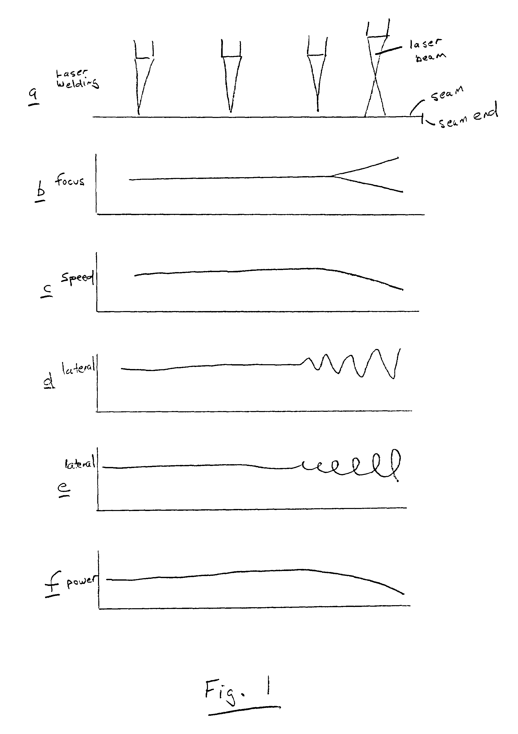
[0011]It is also advantageous when additionally, in proximity to the seam end, the weld speed is reduced, and / or at the seam end a local beam movement extending laterally out beyond the seam occurs.
[0017]Preferably the defocusing of the laser beam takes place increasing linearly. A slope of this type is very easy to achieve from the control technology aspect, and produces an even widening of the laser beam and therewith an even solidification of the melt. For certain applications and / or materials however other focusing progressions can be advantageous, for example a quadratic, or even exponential, increase of the defocusing.
[0021]The greatest advantage is comprised therein, that an easily programmable scanning device can guide the laser beam in very short time interval on almost any processing track over the surface to be processed, and can provide without any problem in particular also precisely defined and coordinated changes of the welding speed or complicated designs or patterns of the lateral beam movement track.

Problems solved by technology

This procedure reduces the problem slightly, but is however frequently insufficient.

Method used


Image

  • Process for laser beam welding with reduced formation of end craters
  • Process for laser beam welding with reduced formation of end craters

Examples


Embodiment Construction

[0034]In the following the inventive process will be described in greater detail on the basis of illustrative embodiments:

[0035]In a first illustrative embodiment steel sheet metal is arranged, and a scanner device is moved evenly thereover deflecting a laser beam over the surface being processed. The scanner device is comprised of a three-dimensional pivotable computer controlled mirror system. The scanner device has approximately 300 mm separation from the surface of the sheet metal, the laser focal point is located on the surface to be welded. Approximately 3 mm before reaching the programmed seam end the focus of the laser beam is distanced from the surface being processed in such a manner that the surface area illuminated by the laser beam increases linearly and incorporates at the seam end a processing surface area equal to approximately another 100% of the focus area. In synchrony with the removal of the focus from the surface, the weld speed is reduced in such a manner that ...


PUM

PropertyMeasurementUnit
Lengthaaaaaaaaaa
Timeaaaaaaaaaa
Poweraaaaaaaaaa

Abstract

During laser beam welding a so-called end crater forms at the end of the weld seam. The end crater is formed by the volume shrinkage of the solidifying melt after the laser beam reaches the seam end and is switched off or repositioned. The end crater acts as a geometric notch and decreases the mechanical characteristics, in particular the operational stability, of the weld seam so that holes or tears in the area of the end crater can occur. The task of the present invention is thus comprised of providing a process for reducing end crater formation. The task is solved in that towards the seam end the focus of the laser beam is distanced from the surface to be welded and / or a transverse movement of the beam occurs.

Description

BACKGROUND OF THE INVENTION[0001]1. Field of Invention[0002]The invention concerns a process for laser beam welding with reduced formation of end craters, according to the precharacterizing portion of Patent Claims 1 and 3. Processes of this general type are already known from DE 196 30 521 A1.[0003]During laser beam welding a so-called end crater forms at the end of the weld seam. The end crater is formed by the volume shrinkage of the solidifying melt after the laser beam reaches the seam end and is switched off or repositioned. The end crater acts as a geometric notch or groove and decreases the mechanical properties, and in particular the operational stability of the weld seam, so that holes or tears in the area of the end crater can occur.[0004]2. Related Art of the Invention[0005]For reducing the formation of end craters, it is taught in DE 196 30 521 A1 to reduce the laser output at the seam end (so-called “power ramp”) or to increase the weld speed (so-called “speed ramp”).[...

Claims


Application Information

Patent Timeline
IPC IPC(8): B23K26/24
CPCB23K26/24
Inventor BECKER, WOLFGANGBECK, MARKUSGOTH, KLAUSPAELMER, MIKEREINIGER, CLAUS-DIETERZAUNER, DANIEL
Owner DAIMLER AG
Learn More