Voltage generator with reduced noise

a voltage generator and noise reduction technology, applied in the direction of electric generator control, dynamo-electric converter control, instruments, etc., can solve the problems of destabilizing power sources and unnecessary power consumption, and achieve the effect of reducing the fluctuation of driving voltage vpp

Active Publication Date: 2006-08-15
SK HYNIX INC
View PDF22 Cites 27 Cited by
  • Summary
  • Abstract
  • Description
  • Claims
  • Application Information

AI Technical Summary

Benefits of technology

[0011]The present invention has an object to reduce fluctuation of driving voltage Vpp by pumping a predetermined amount of charge according to an operation of a DRAM when the driving voltage Vpp reaches a predetermined level before a target level.
[0012]In an embodiment of the present invention there is provided a voltage generator comprising: a detector for comparing an output voltage with a first reference voltage and a second reference voltage lower than the first reference voltage to output a first sensing signal and a second sensing signal; a controller for receiving the first sensing signal and the second sensing signal, and an action signal to output a first control signal and a second control signal; a sub-booster for boosting a voltage in response to the first control signal; a main booster for boosting a voltage in response to the second control signal; and a voltage adder for adding output signals from the sub-booster and the main booster to provide the output voltage.

Problems solved by technology

As described above, in the conventional voltage generator, fluctuation ΔVpp of the driving voltage Vpp becomes large, due to the time delay between the point when the detector 10 actually detects the target level and the point when the pump 40 starts or stops operating, which results in unnecessary power consumption.
Importantly, this fluctuation of the driving voltage causes noise that may destabilize the power source.

Method used


Image

  • Voltage generator with reduced noise
  • Voltage generator with reduced noise
  • Voltage generator with reduced noise

Examples


Embodiment Construction

[0022]The present invention will be described in detail with reference to the attached drawings.

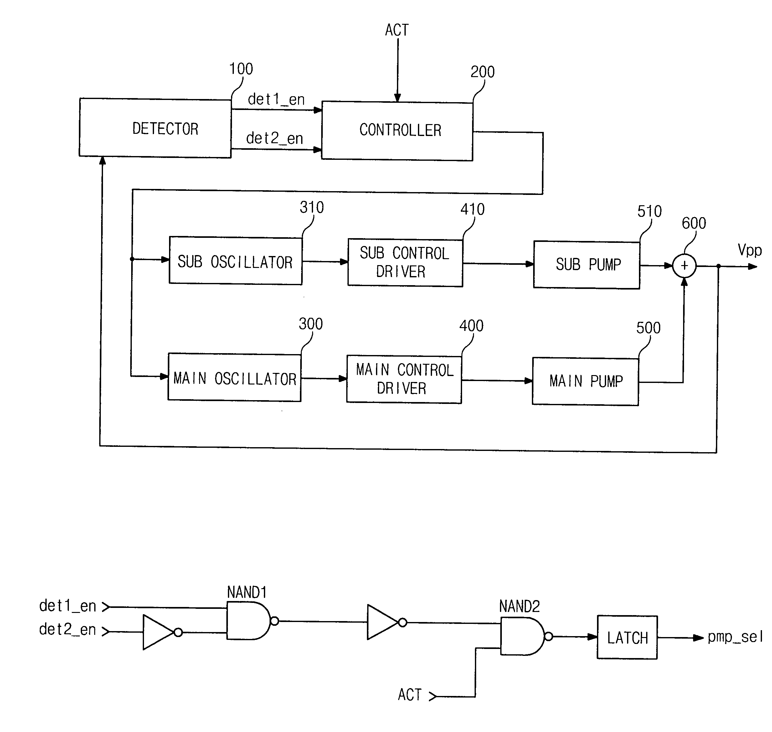
[0023]FIG. 4 is a block diagram illustrating a voltage generator according to an embodiment of the present invention.

[0024]In this embodiment, the disclosed voltage generator comprises a detector 100, a controller 200, a main oscillator 300, a sub-oscillator 310, a main control driver 400, a sub-control driver 410, a main pump 500, a sub-pump 510 and a voltage adder 600. The detector 100 has more than two detection levels. The controller 200 outputs a control signal when an action signal ACT is inputted after a driving voltage Vpp passes a predetection level and before a driving voltage Vpp reaches a target level. The main oscillator 300 and the sub-oscillator 310 output oscillating signals in response to the control signal outputted from the controller 200. The main control driver 400 and the sub-control driver 410 output pump control signals in response to the oscillating signals output...


PUM


Abstract

A voltage generator with reduced noise features a detector, a controller, a sub-booster, a main booster and a voltage adder. The detector receives an output voltage, a first reference voltage and a second reference voltage lower than the first reference voltage, and then outputs a first sensing signal and a second sensing signal. The controller receives the first sensing signal and the second sensing signal and an action signal to output a first control signal and a second control signal. The sub-booster boosts a voltage in response of the first control signal. The main booster boosts a voltage in response to the second control signal. The voltage adder adds output signals from the sub-booster and main booster, to provide the output voltage.

Description

BACKGROUND OF THE INVENTION[0001]1. Field of the Invention[0002]The present invention generally relates to voltage generators, and more specifically, to a charge-pumping type voltage generator configured to reduce noise.[0003]2. Description of the Prior Art[0004]In conventional DRAMs, charges are pumped to generate a driving voltage for driving wordlines and bitlines without loss of threshold voltage. During DRAM operations, such as wordline-driving and bitline-precharging, a great amount of energy is consumed and then a level of the driving voltage becomes lower. In this case, the time when the level of the driving voltage becomes lower than a target level is detected in the conventional art to pump charges and maintain the level of the driving voltage.[0005]FIG. 1 is a block diagram illustrating a conventional voltage generator. The conventional voltage generator comprises a detector 10, an oscillator 20, a control driver 30 and a pump 40. The detector 10 detects a level of a driv...

Claims


Application Information

Patent Timeline
Patent Type & Authority Patents(United States)
IPC IPC(8): G05F1/10G05F3/24G11C5/14H02M3/07
CPCH02M3/073H02M2003/077H02M3/077G11C5/14
Inventor KWON, MYEONG JULEE, JAE JIN
Owner SK HYNIX INC
Why Eureka
Try Eureka