System and method for sensing a characteristic of a fluid and related apparatus

a technology of sensing and characteristic, applied in the field of sensing, detecting, or measuring a characteristic of a fluid, can solve the problems of affecting the sensing accuracy, disrupting the fluid flow, and typically projecting transversely the transmitter and receiver, so as to promote smooth fluid flow and facilitate cleaning

Inactive Publication Date: 2006-08-15
UNIV OF KENTUCKY RES FOUND
View PDF16 Cites 15 Cited by
  • Summary
  • Abstract
  • Description
  • Claims
  • Application Information

AI Technical Summary

Benefits of technology

[0009]Preferably, the body is a single piece of material, the first and second sidewalls are opposed, and the first and second passage are formed using a single tool during a continuous machining process. This is done to ensure proper alignment among the first and second optical mediums when positioned in a transmission configuration. The pocket is partially defined by a generally U-shaped bottom wall. As should be appreciated, this shape or contour promotes smooth fluid flow and easy cleaning.

Problems solved by technology

While this “transmision” type of sensor arrangement generally permits taking of the desired measurements in an acceptable manner, there are several well-recognized limitations.
One significant limitation is that the transmitter and receiver typically project transversely into the fluid flow from the outer wall of the pipeline.
Of course, this positioning severely disrupts the fluid flow and may have a deleterious effect on the sensing accuracy.
The large physical distance (path length) also limits transmission measurements to relatively clear fluids.
However, one of the technical problems with a protruding optical means having a short path length is stability.
For example, vibrations, and especially thermal movement of the wall, results in relatively large displacement in the path length.
This increases signal error, especially in highly turbid fluids.
However, this increases the path length and complicates the arrangement.

Method used


Image

  • System and method for sensing a characteristic of a fluid and related apparatus
  • System and method for sensing a characteristic of a fluid and related apparatus
  • System and method for sensing a characteristic of a fluid and related apparatus

Examples


Embodiment Construction

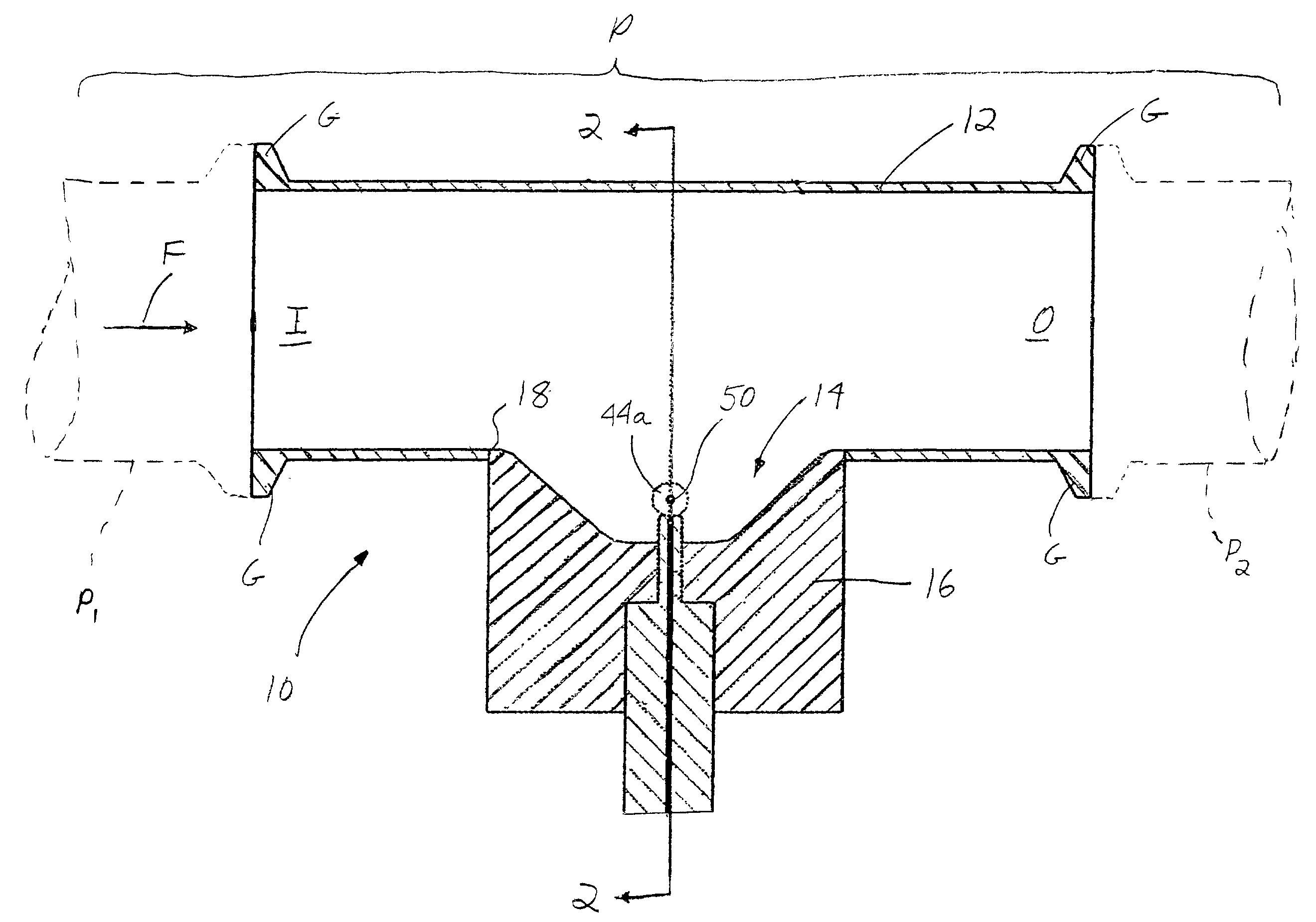
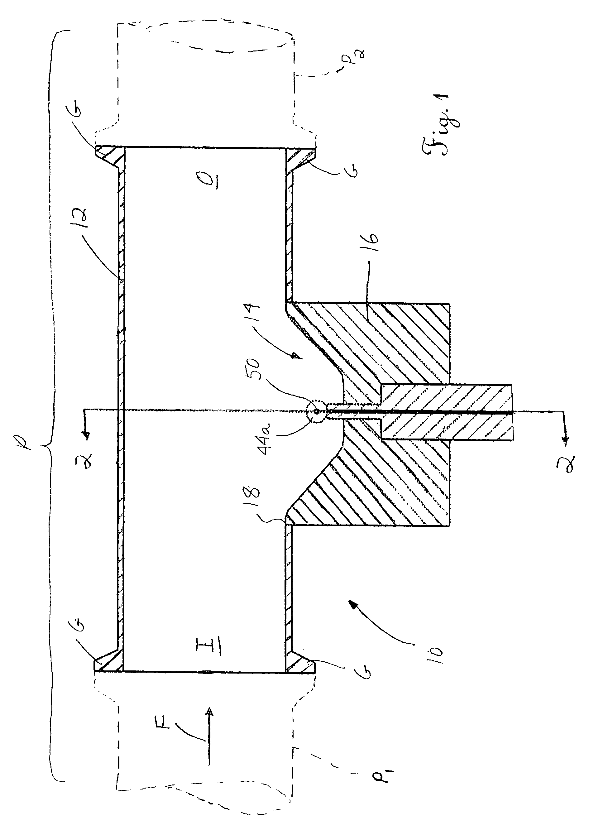
[0020]Reference is now made to FIG. 1, which shows a pipe segment 10 including the apparatus of the present invention. The segment 10 includes an inlet I for receiving a fluid F, such as a liquid food product (e.g., milk) flowing from an upstream pipe segment P1 in a pipeline P and an outlet O for discharging the flow to a downstream pipe segment P2. The portion of the segment 10 for receiving the fluid F includes an outer wall 12. The outer wall 12 may have a substantially circular cross-section, although other cross-sectional shapes can be used as necessary or desired for a particular application. Oversized annular flanges G may be provided at the ends of the cylindrical wall 12 for mating with corresponding flanges on pipe segments P1, P2. As should be appreciated, these flanges G when mated with the corresponding flanges on the adjacent pipe segments P1, P2 create an interface capable of receiving a clamp or other attachment means (not shown) such that a secure, fluid-impervious...


PUM

PropertyMeasurementUnit
optical path lengthaaaaaaaaaa

Abstract

An apparatus for intended use in measuring, sensing, or detecting a characteristic of a fluid, such as a liquid food product, is disclosed. The apparatus includes a body having a pocket for positioning adjacent to the opening in a pipe or like structure for receiving a portion of a fluid therein. In one possible use, a first optical medium, such as an optical fiber, transmits light from a source toward a portion of the fluid flow entering the pocket. Light received by one or more optical mediums positioned in backscatter, sidescatter, or transmission configurations relative to the first optical medium is detected by a corresponding sensor or detector. Using the output of this sensor or detector, an optical characteristic of the fluid may be measured. An overall system using the apparatus and related method for detecting an optical characteristic of a fluid are also disclosed.

Description

TECHNICAL FIELD[0001]The present invention relates to the art of sensing, detecting, or measuring a characteristic of a fluid, such as a liquid food product. More particularly, the present invention relates to an improved apparatus for use in detecting light transmitted through or reflected by a fluid flowing along a pipeline, along with a system incorporating the apparatus and a related method.BACKGROUND OF THE INVENTION[0002]The food, pharmaceutical, and chemical industries rely heavily on the use of devices for measuring, sensing, or detecting characteristics of a fluid, such as a liquid containing particles. For example, optical sensors are frequently used to detect characteristics of milk in an effort to determine the amount of a particular component present, such as milkfat or casein. The amount of the component detected or sensed then determines whether the fluid meets a certain criteria before undergoing further processing or whether it is suitable for a particular use (i.e....

Claims


Application Information

Patent Timeline
Patent Type & Authority Patents(United States)
IPC IPC(8): G01N1/10G01N21/05G01N21/53
CPCG01N21/532G01N21/05
Inventor PAYNE, FRED A.
Owner UNIV OF KENTUCKY RES FOUND
Why Eureka
Try Eureka