Bidirectional wavelength division multiplexed self-healing ring network composed of add fiber and drop fiber

a self-healing ring network and wavelength division technology, applied in multiplex communication, instruments, optical elements, etc., can solve the problems of complex structure of the remote node, deteriorating signal quality, and using expensive optical amplifiers

Inactive Publication Date: 2006-08-15
KOREA ADVANCED INST OF SCI & TECH
View PDF4 Cites 7 Cited by
  • Summary
  • Abstract
  • Description
  • Claims
  • Application Information

AI Technical Summary

Benefits of technology

[0020]Optical signals are bidirectionally transmitted from the central office to the remote nodes. Thus, even in the case

Problems solved by technology

Therefore, the quality of signals is deteriorated and expensive optical amplifiers may be employed to compensate for a loss due to the increased transmission distance.
Additionally, in the conventional optical ring networ

Method used


Image

  • Bidirectional wavelength division multiplexed self-healing ring network composed of add fiber and drop fiber
  • Bidirectional wavelength division multiplexed self-healing ring network composed of add fiber and drop fiber
  • Bidirectional wavelength division multiplexed self-healing ring network composed of add fiber and drop fiber

Examples


first embodiment

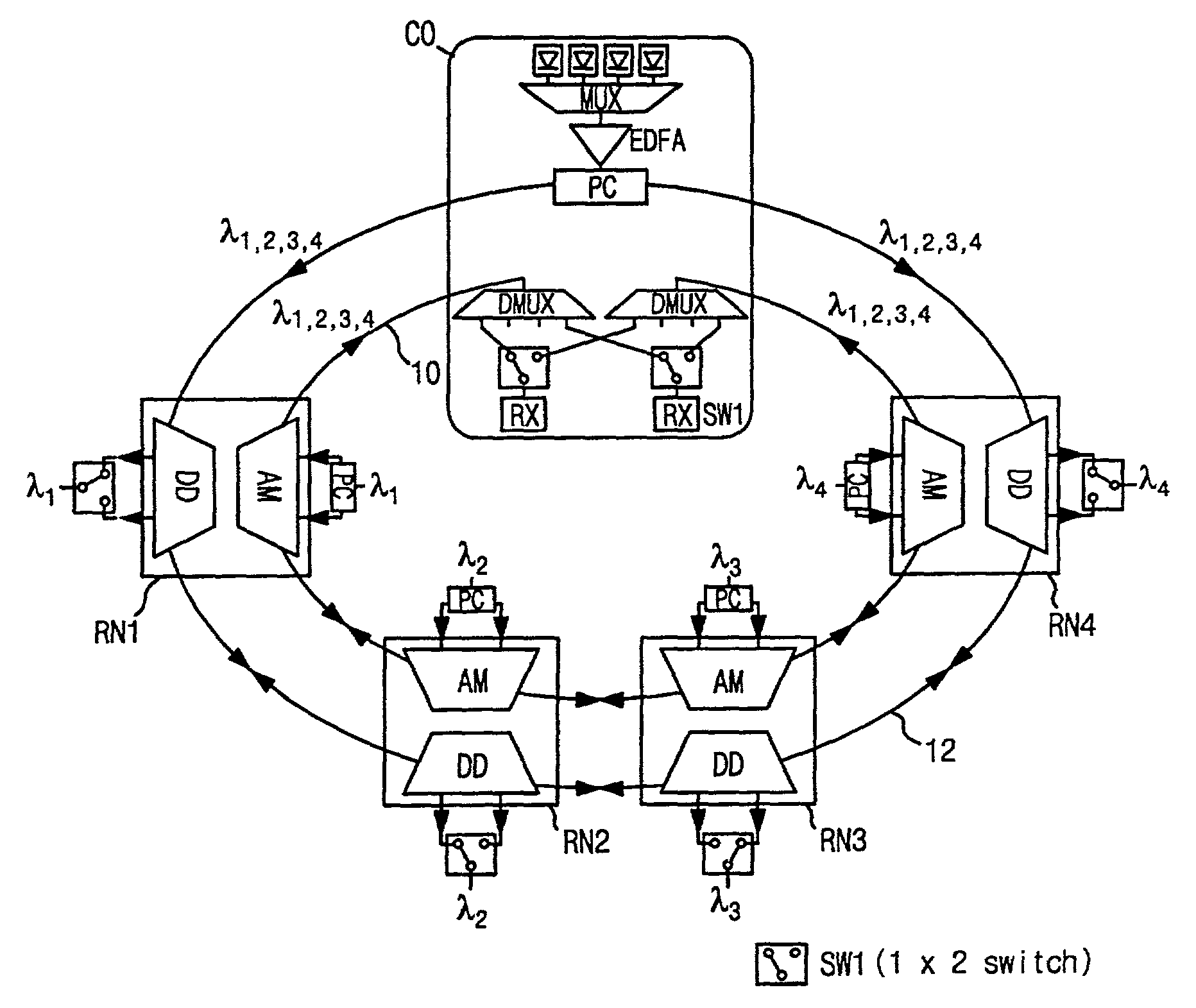
[0041]FIG. 1 is a diagram showing a configuration of a bidirectional wavelength division multiplexed self-healing ring network in accordance with the present invention. The bidirectional wavelength division multiplexed self-healing ring network includes two optical fibers that constitute an add fiber 10 and a drop fiber 12, respectively.

[0042]A central office CO is divided into a wavelength division multiplexed optical receiving part and a wavelength division multiplexed optical transmission part. The wavelength division multiplexed optical transmission part is connected to the drop fiber 12 through its both transmission terminals, while the wavelength division multiplexed optical receiving part is connected to the add fiber 10 through its both receiving terminals.

[0043]Remote nodes RN1, RN2, RN3 and RN4 are each composed of an add multiplexer AM and a drop demultiplexer DD. The add fiber 10 is connected to both terminals of the add multiplexer AM, while the drop fiber 12 is connect...

second embodiment

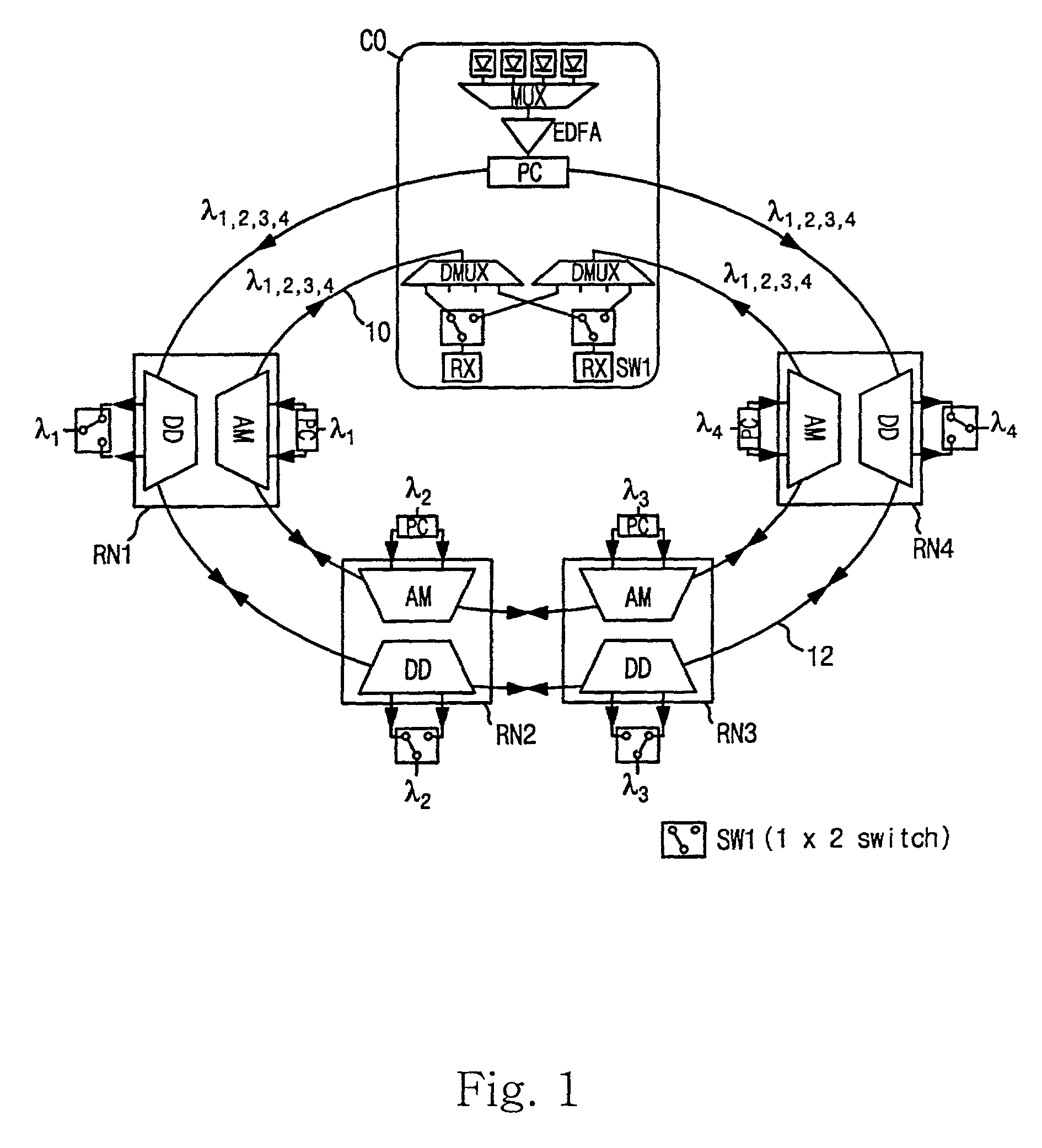
[0054]FIG. 2 is a diagram showing a configuration of a bidirectional wavelength division multiplexed self-healing ring network in accordance with the present invention. This drawing shows the case, where the wavelengths of signals added are different from the wavelengths of signals dropped.

[0055]The wavelengths of signals added in remote nodes RN1, RN2, RN3 and RN4 can be made to be different from the wavelengths of signals dropped in remote nodes RN1, RN2, RN3 and RN4 in such a way that wavelengths λ1, λ2, λ3 and λ4 of wavelength division multiplexed optical signals transmitted from the central office CO to the remote nodes RN1, RN2, RN3 and RN4 are made to be different from wavelengths λa, λb, λc and λd of wavelength division multiplexed optical signals transmitted from the remote nodes RN1, RN2, RN3 and RN4 to the central office CO.

[0056]A path of the optical signals transmitted from the remote nodes RN1, RN2, RN3 and RN4 to the central office CO is separated from a path of the o...

third embodiment

[0066]FIG. 4 is a diagram showing a bidirectional wavelength division multiplexed self-healing ring network in accordance with the present invention. The wavelength division multiplexed optical signals transmitted bidirectioally have the same wavelength but are modulated with different data.

[0067]Two groups of optical signals transmitted bidirectionally from the central office CO are allowed to have the same wavelengths, and modulated with different data by two kinds of optical modulators (not shown). A pair of differently modulated signals having the same wavelength are applied to two terminals of a 2×2 optical switch SW2, and two other terminals of the 2×2 optical switch SW2 are connected to the assigned input terminals of two multiplexers MUXs, respectively. The 2×2 optical switch SW2 establishes a path of optical signals so that wavelength signals modulated with the higher priority data may be transmitted in a counterclockwise direction in a normal state.

[0068]Accordingly, two g...


PUM


Abstract

Disclosed herein is a bidirectional wavelength division multiplexed self-healing ring network. The ring network includes a central office and a plurality of remote nodes. Two optical fibers each connect the central office and the remote nodes in a ring form to allow optical signals to be bidirectionally received and transmitted between the central office and the remote nodes. One of the two optical fibers is a drop fiber for transmitting optical signals from the central office to the remote nodes, while the other is an add fiber for transmitting optical signals from the remote nodes to the central office.

Description

BACKGROUND OF THE INVENTION[0001]1. Field of the Invention[0002]The present invention relates generally to a wavelength division multiplexed self-healing network, and more particularly to a bidirectional wavelength division multiplexed self-healing ring network, in which a central office and remote nodes are connected to one another using two optical fibers—add fiber and drop fiber. Optical signals are transmitted bidirectionally through the two optical fibers. And, the proposed ring network provides the self-healing function without the protection optical switch in the transmission path and doubles the transmission capacity in a normal operating state.[0003]2. Description of the Prior Art[0004]As the amount of the desired transmission traffic increases by the popularization of the Internet, the interest in optical networks that connect a central office to subscribers grows up.[0005]The optical network should facilitate the provision of high-speed service to fulfill a demand for the...

Claims


Application Information

Patent Timeline
IPC IPC(8): H04B10/20H04J14/02
CPCH04J14/0206H04J14/0209H04J14/021H04J14/0212H04J14/0213H04J14/0241H04J14/0227H04J14/0283H04J14/0294H04J14/0295H04J14/0216
Inventor LEE, CHANG HEEPARK, SUNG BUM
Owner KOREA ADVANCED INST OF SCI & TECH
Why Eureka
Try Eureka