Ruggedized placard

Active Publication Date: 2017-11-30
OPTIC CLEAR SOLUTIONS LLC
View PDF2 Cites 1 Cited by
  • Summary
  • Abstract
  • Description
  • Claims
  • Application Information

AI Technical Summary

Benefits of technology

The present invention is a rugged placard design that can withstand extreme environments and high wear applications such as long periods of sunlight. It also manages reflective glare and is easy to clean with water. The placard is resistant to damage from solvents, salt exposure, and petroleum based fuels. It can be applied to curved surfaces or formed to fit unusual surfaces. The placard provides long life and high visibility indicia that is clearly presented to observers.

Problems solved by technology

While many designs for placards exist and users are typically loathe to experiment with new and untested designs, applicants believe useful improvements provide, among other things, survivability of information carried by the placard.

Method used


Image

  • Ruggedized placard
  • Ruggedized placard
  • Ruggedized placard

Examples


Embodiment Construction

[0024]The disclosure provided in the following pages describes examples of some embodiments of the invention. The designs, figures and description are non-limiting examples of the embodiments they disclose. For example, other embodiments of the disclosed device and / or method may or may not include the features described herein. Moreover, disclosed advantages and benefits may apply to only certain embodiments of the invention and should not be used to limit the disclosed invention.

[0025]As used herein, the terms “coupled” and “attached” include direct and indirect connections. Moreover, where first and second devices are coupled or attached, intervening devices including active devices may be located therebetween.

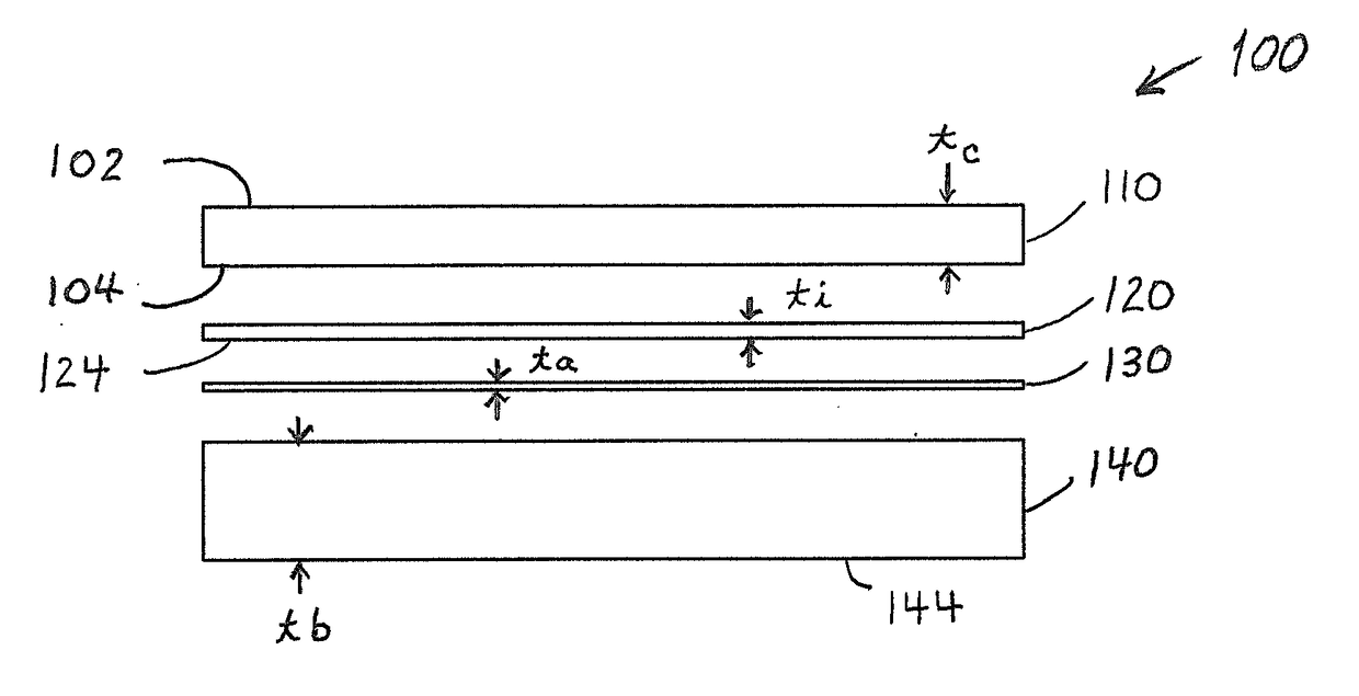
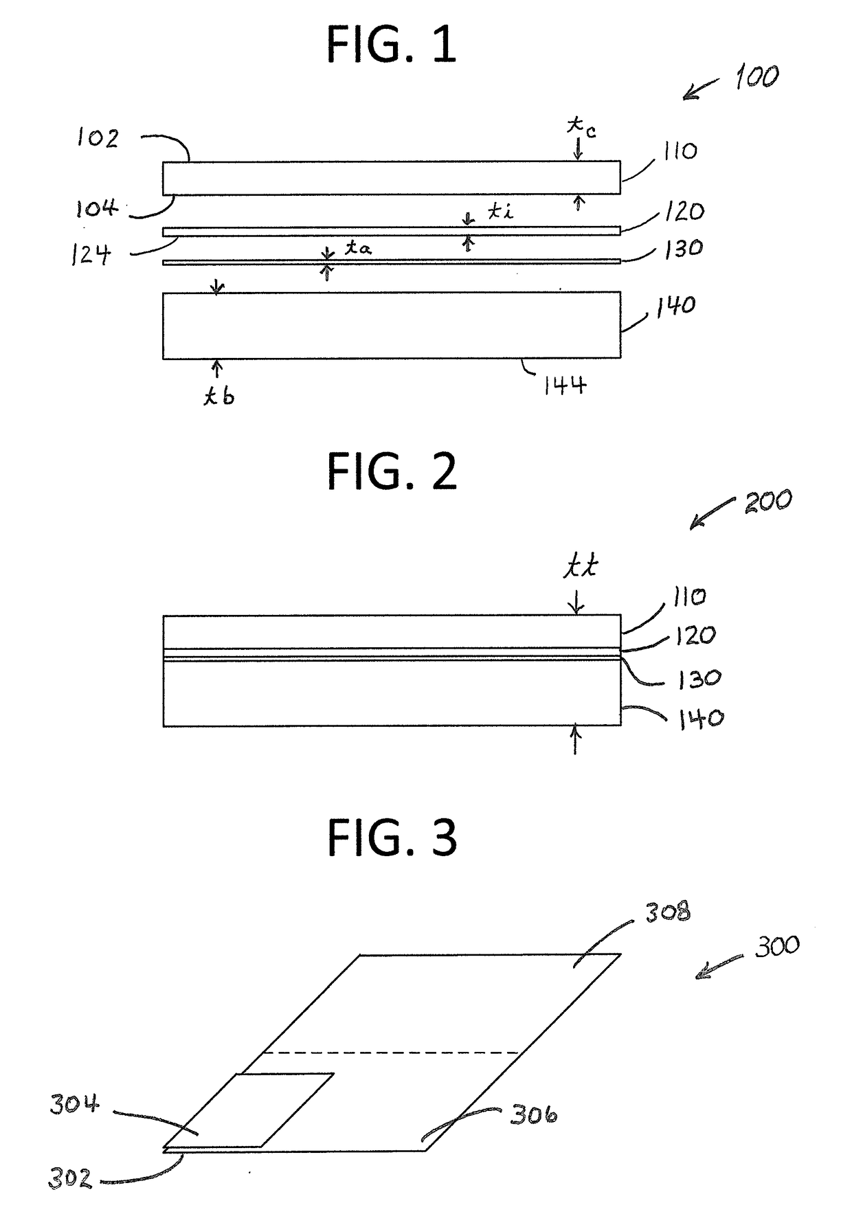
[0026]FIGS. 1-2 illustrate layers of a ruggedized placard of the present invention 100. In FIG. 1, the placard view is an exploded view 100. In FIG. 2, the placard view is an assembly view 200. As shown, an indicia layer 120 is located beneath a cover layer 110. An optional ...


PUM

PropertyMeasurementUnit
Fractionaaaaaaaaaa
Fractionaaaaaaaaaa
Fractionaaaaaaaaaa

Abstract

A ruggedized placard utilizes a multilayer construction including a clear primary layer or cover and an indicia layer, the indicia being viewable through the clear primary layer.

Description

INCORPORATION BY REFERENCE[0001]This application incorporates by reference, in their entireties and for all purposes, the disclosure of U.S. Pat. No. 5,466,756 concerning polymethylmethacrylate and cell cast polymethylmethacrylate, and U.S. Pat. No. 5,182,148 concerning colorants.BACKGROUND OF THE INVENTIONField of the Invention[0002]The present invention relates to optics and optical devices. In particular, a multilayer placard withstands physical abuse while continuing to provide high visibility signage.Discussion of the Related Art[0003]It is known that placards are common place in numerous forms and applications within our society at large. These placards are found bearing information that is useful and helpful in our daily lives. Some placards provide us with advertising while others provide us information to what is dangerous and harmful.[0004]It should be understood that placards exist for the betterment of society. It should also be understood that these placards can age / wea...

Claims


Application Information

Patent Timeline
IPC IPC(8): G09F15/00B29C69/02B29C53/04B29C59/02B29C65/48B29K33/00B29K105/00B29L31/00
CPCG09F15/0012B29C69/02B29C65/48B29L2031/7232B29C59/02B29K2033/12B29K2105/256B29C53/04B29C53/84G09F1/02G09F7/165B32B7/12B32B15/12B32B15/08B32B27/10B32B27/08B32B2250/02B32B2250/03B32B2250/40B32B27/308B32B27/365B32B2255/10B32B2255/26B32B2307/584B32B2307/542B32B2307/732B32B2307/58B32B2307/734B32B2307/714B32B2307/4023B32B2307/404B32B2307/4026B32B2425/00B32B27/00
Inventor TRUONG, SAMKOLHELSTERN, ROBERT P.
Owner OPTIC CLEAR SOLUTIONS LLC
Why Eureka
Try Eureka