Rolling mill coil forming laying head with path or pipe having dissimilar materials composite construction

Inactive Publication Date: 2013-03-28
SIEMENS IND INC
View PDF3 Cites 6 Cited by
  • Summary
  • Abstract
  • Description
  • Claims
  • Application Information

AI Technical Summary

Benefits of technology

[0019]Briefly described, embodiments of the present invention relate to a rolling mill coil-forming apparatus laying head path structure, for retention and transport of elongated materials in a laying head, so that the elongated material can be selectively coiled. The laying head path structure may perform the functionality of a conventional laying head pipe, In aspects of the present invention, the laying head path structure comprises combinations of ferrous and non-ferrous dissimilar materials. Non-ferrous materials can be used in zones that are subject to relatively higher wear, and ferrous materials, such as steel, can be used in zones t

Problems solved by technology

But commercial steel pipe or tubing have relatively low hardness: an undesirable limiting factor for rolling mill operation, productivity and maintenance.
At such speeds, the hot rolled products exert a punishing effect on the laying head pipes, causing internal pipe surfaces to undergo rapid localized frictional wear and premature failure.
Also, as the laying head pipes wear, their ability to deliver a stable ring pattern to the looped coil receiving conveyor at the discharge end of the laying head deteriorates.
Unstable ring patterns disturb cooling uniformity and also contribute to coiling mishaps commonly referred to as “cobbling.”
Unfortunately, however, these advantages have been offset to a large extent by significantly accelerated pipe wear due to the higher speed of the product.
Also, the reduced bore size pipe can only be used with small diameter products, so it must be replaced by a larger bore size pipe for coiling of larger diameter products.
Frequent and costly mill shutdowns and preventive maintenance are required to replace prematurely worn laying head pipes and to address problems associated with elongated material cobbling.
If a laying hea

Method used


Image

  • Rolling mill coil forming laying head with path or pipe having dissimilar materials composite construction
  • Rolling mill coil forming laying head with path or pipe having dissimilar materials composite construction
  • Rolling mill coil forming laying head with path or pipe having dissimilar materials composite construction

Examples


Example

[0044]To facilitate understanding, identical reference numerals have been used, where possible, to designate identical elements that are common to the figures.

DETAILED DESCRIPTION

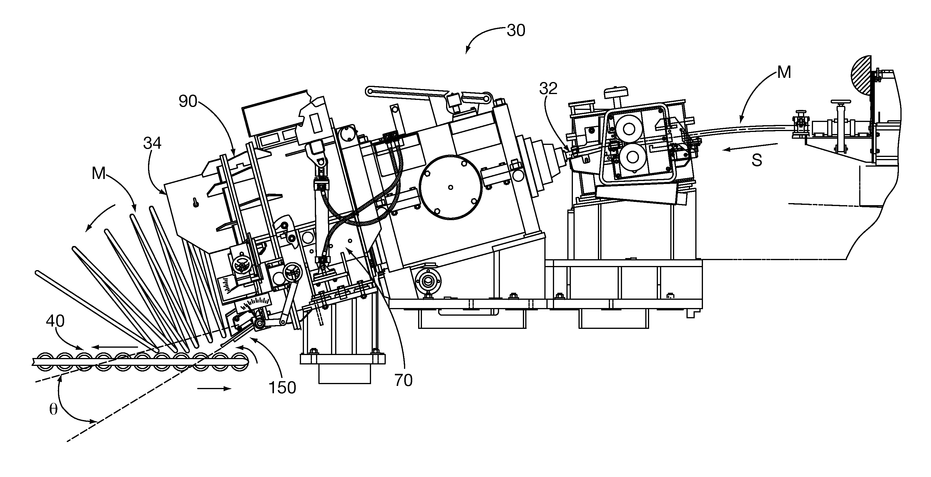
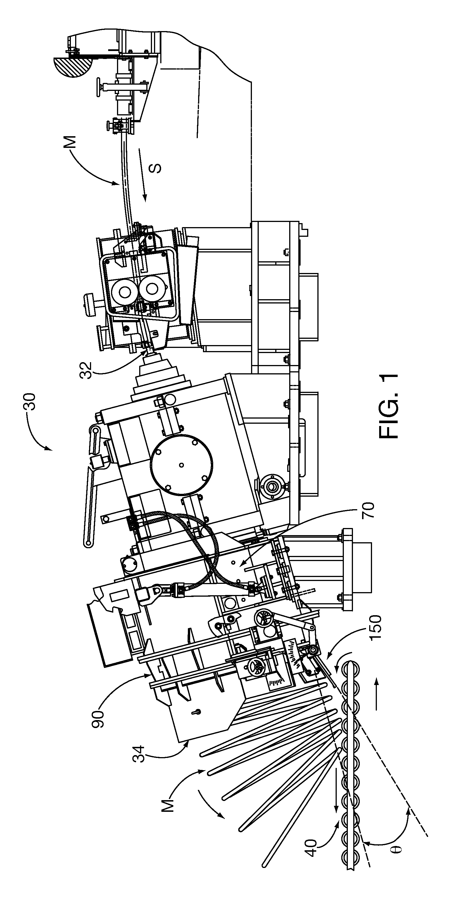
[0045]After considering the following description, those skilled in the art will realize that the teachings of the present invention can be utilized in rolling mill coil-forming apparatus laying heads and more particularly to laying head elongated transport path pipes or other equivalent elongated structures for laying heads. Aspects of the present invention facilitate longer laying head path service life so that more tons of elongated material can be processed by the laying head before preventative maintenance replacement. For example, it is possible to increase the laying head elongated material processing speed so that more tons of elongated material can be processed in a production shift without undue risk of laying head path / pipe failure.

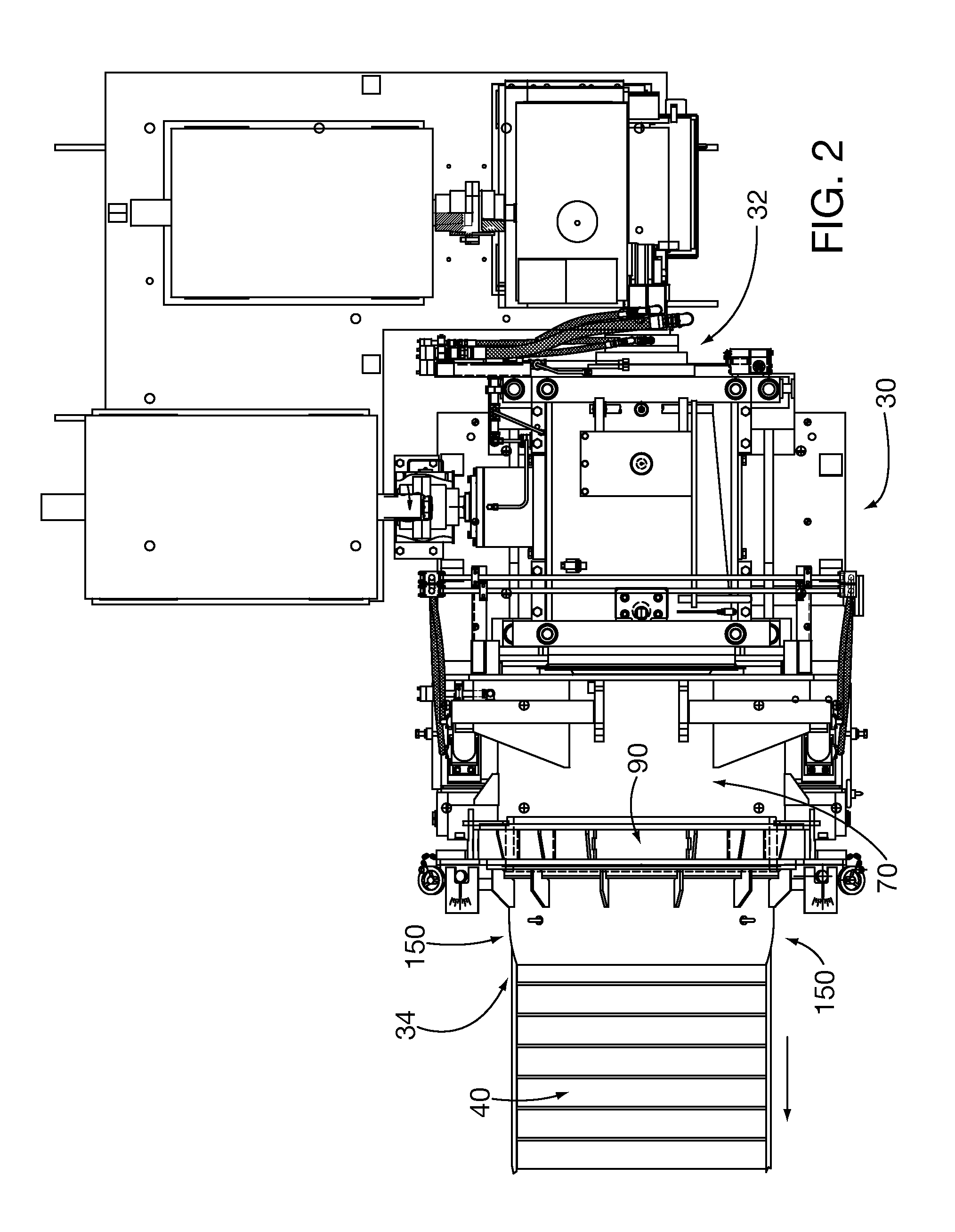
[0046]Laying Head System Overview

[0047]Referring generally to FI...


PUM

PropertyMeasurementUnit
Frictionaaaaaaaaaa
Wear rateaaaaaaaaaa

Abstract

A rolling mill coil-forming apparatus includes a rotating quill that discharges elongated material into an elongated path hollow structure, such as a laying head pipe. The elongated structure is constructed of combinations of ferrous and non-ferrous dissimilar materials. Generally, non-ferrous materials are used in zones that are subject to relatively higher wear. A portion of the elongated path structure can be formed from nested, enveloping layers and/or by joining segments in axial abutting relationship. Components formed from nested layers can be constructed in many three dimensional compound curve shapes that can replicate the smooth, continuous curve elongated material transport path laying head pipes, with localized symmetrical or asymmetrical cross sections.

Description

CROSS-REFERENCE TO RELATED APPLICATIONS [0001]This application claims priority under 35 U.S.C. §119(e) to co-pending U.S. Provisional Application Ser. Nos.: 61 / 539,014, 61 / 539,062, and 61 / 539,069, filed 26 Sep. 2011; and U.S. Provisional Application Ser. Nos.: 61 / 540,590; 61 / 540,602; 61 / 540,609; 61 / 540,617; and 61 / 540,798; filed 29 Sep. 2011, and all of which are entirely incorporated herein by reference as if fully set forth below.BACKGROUND[0002]1. Field[0003]Embodiments of the present invention relate to rolling mill coil-forming apparatuses, often referred to as laying heads, and more particularly to replaceable laying head pathways, such as laying head pipes, in laying heads.[0004]2. Description of the Prior Art[0005]Rolling mill coil-forming laying head apparatuses form moving rolled elongated material into a series of helical continuous loop rings. Those rings may be further processed downstream by bundling them into coils of the helical turns. Known laying heads are describe...

Claims


Application Information

Patent Timeline
IPC IPC(8): B21C47/08B23P11/00B23P17/04
CPCB21C47/143B65H57/12B65H2402/10Y10T29/49826Y10T29/49Y10T29/4973B65H2701/36B33Y80/00
Inventor FIORUCCI, KEITH
Owner SIEMENS IND INC
Why Eureka
Try Eureka