Conveyor belt cleaning system

a belt cleaning and conveyor technology, applied in the direction of conveyor parts, cleaning, transportation and packaging, etc., can solve the problems of increasing the impact load of the cleaning blade, the angle of attack relative, and the problem of exacerbated problems, so as to reduce the load thereon

Inactive Publication Date: 2006-08-22
FLEXIBLE STEEL LACING
View PDF68 Cites 51 Cited by
  • Summary
  • Abstract
  • Description
  • Claims
  • Application Information

AI Technical Summary

Benefits of technology

[0012]In accordance with one aspect of the invention, a cleaner for a conveyor belt is provided having a blade mount member for resiliently keeping a scraper blade in engagement against the belt. The blade mount member has a layback portion and a lower arcuate portion. The layback portion has the scraper blade secured to an upper end thereof and extends at a layback angle toward the belt with the lower arcuate portion spaced upstream of the upper end of the layback portion. The lower arcuate portion flexes during conveyor belt operations for controlled deflection of the layback portion that reduces loading thereon and substantially keeps the scraper blade engaged against the belt.

Problems solved by technology

In heavier duty applications, this problem can be exacerbated by the use of thicker, more robust fasteners which create higher impact loads on the cleaning blade.
Another problem for keeping the blade in contact with the belt is its angle of attack relative to the belt.
Generally, scalping angles where the blade leans forwardly or in the upstream direction as the belt travels downstream so as to form an obtuse angle with the belt surface upstream therefrom presents the most problems.
Also, these high impact forces can cause the blade to vibrate or “chatter” along the belt surface rather than staying in conformance with the belt reducing the cleaning efficiency of the blade.
Catastrophic failure of the cleaner blade mounting components utilizing scalping angles is also of greater concern.
Similarly, while a cleaning blade extending normal or vertically with respect to the belt surface to be cleaned is more desirable for cleaning, cleaning systems employing blade mounting members that only provide for vertical blade movements still can create high impact forces, particularly on belt splices which can cause excessive wear and ultimate failure of the splices.
By contrast, having the blade extending in the downstream direction so that it forms an acute angle with the belt surface upstream therefrom reduces the impact loading on the blade but can also create difficulties in keeping the blade in conformance with the belt surface.
Unless the blade is heavily tensioned into engagement with the belt, when the blade encounters even minor surface irregularities or variations in contour on the belt surface it will undesirably shift too far away from the belt.
In other words, the sensitivity of the blade is not optimized in terms of its ability to stay in substantial contact with the belt surface when encountering relatively small irregularities in the surface of the belt that do not cause undue wear of the blade.
Accordingly, when these irregularities are due to small pieces of material being carried back on the return run of the belt, the acutely angled blade may not be effective in scraping these off the belt surface.
Another problem with the acute angle of the blade is that any of the blade mounts extending at the same angle will have the material scraped from the conveyor belt surface falling thereon.
If this material build-up increases, it can impair the ability of the scraper blade to effectively clean the belt surface.
Generally, these biasing mechanisms have been characterized by their complexity in an effort to enhance cleaning efficiency while reducing blade wear.
Particularly, the pivot biasing mechanisms typically employ several pivots and linkages between the conveyor frame and the blade, as well as separate springs such that there are several components which makes these systems more susceptible to wear and failure, see e.g. U.S. Pat. No. 3,952,863 to Schattauer.
These types of conveyor systems generally will not be effective in high temperature conditions where the material that is being conveyed and / or the surrounding environment can be at elevated temperatures, such as conveyor belts running at asphalt and cement facilities.
To this end, material creep for these materials can become a serious problem particularly in high temperature environments where creep can be accelerated.
Likewise, the ability of polymeric or elastomeric creep materials undergoing accelerated creep to apply the same bias force to the blade over time will be compromised, as they may lose their ability to return to their original, relaxed configuration with excessive applied stress over long time durations.
Another problem with belt cleaning systems employing resilient biasing mechanisms for urging the cleaning blade into scraping engagement with the belt is the impact force with which the blade is returned into engagement with the belt after shifting away therefrom.
In many prior systems, it is very difficult to quickly reengage the belt with a cleaning blade that has resiliently shifted away therefrom without returning back into engagement with the belt with an unduly high impact force.
The blade impacting against the splice fasteners with high force can damage these fasteners decreasing splice life.

Method used


Image

  • Conveyor belt cleaning system
  • Conveyor belt cleaning system
  • Conveyor belt cleaning system

Examples


Embodiment Construction

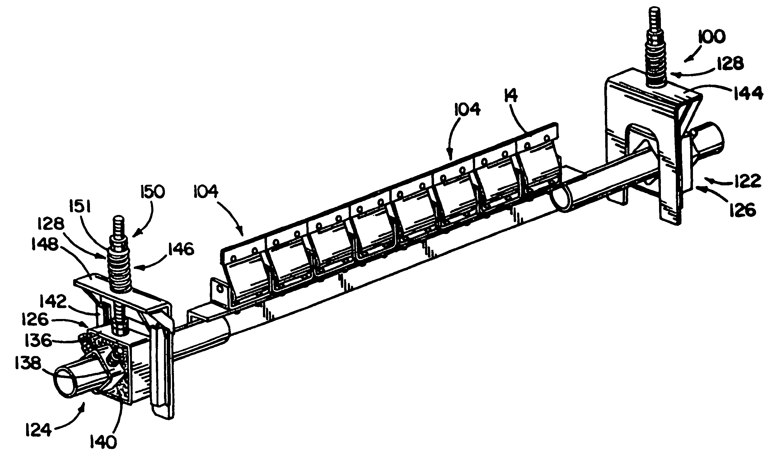
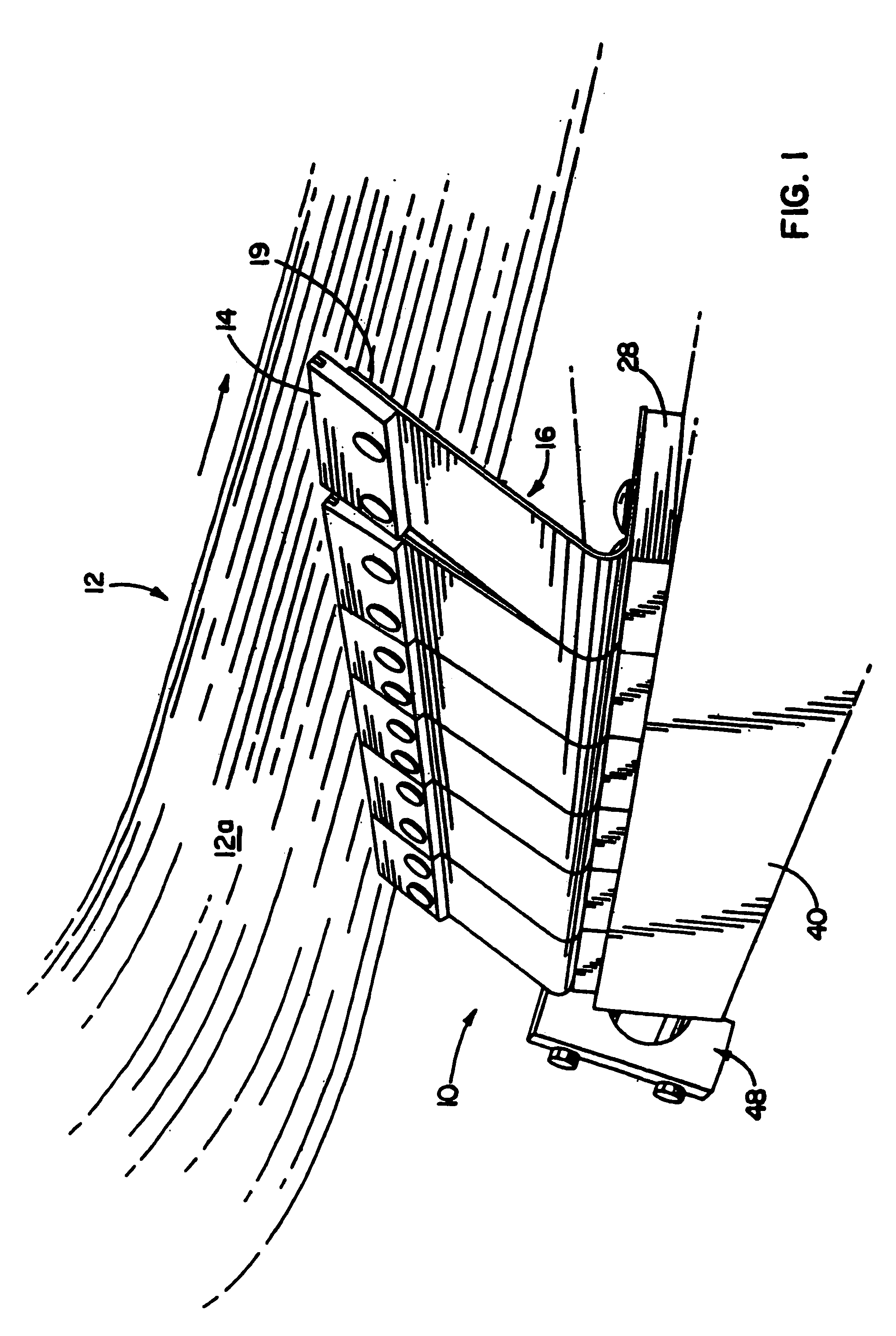
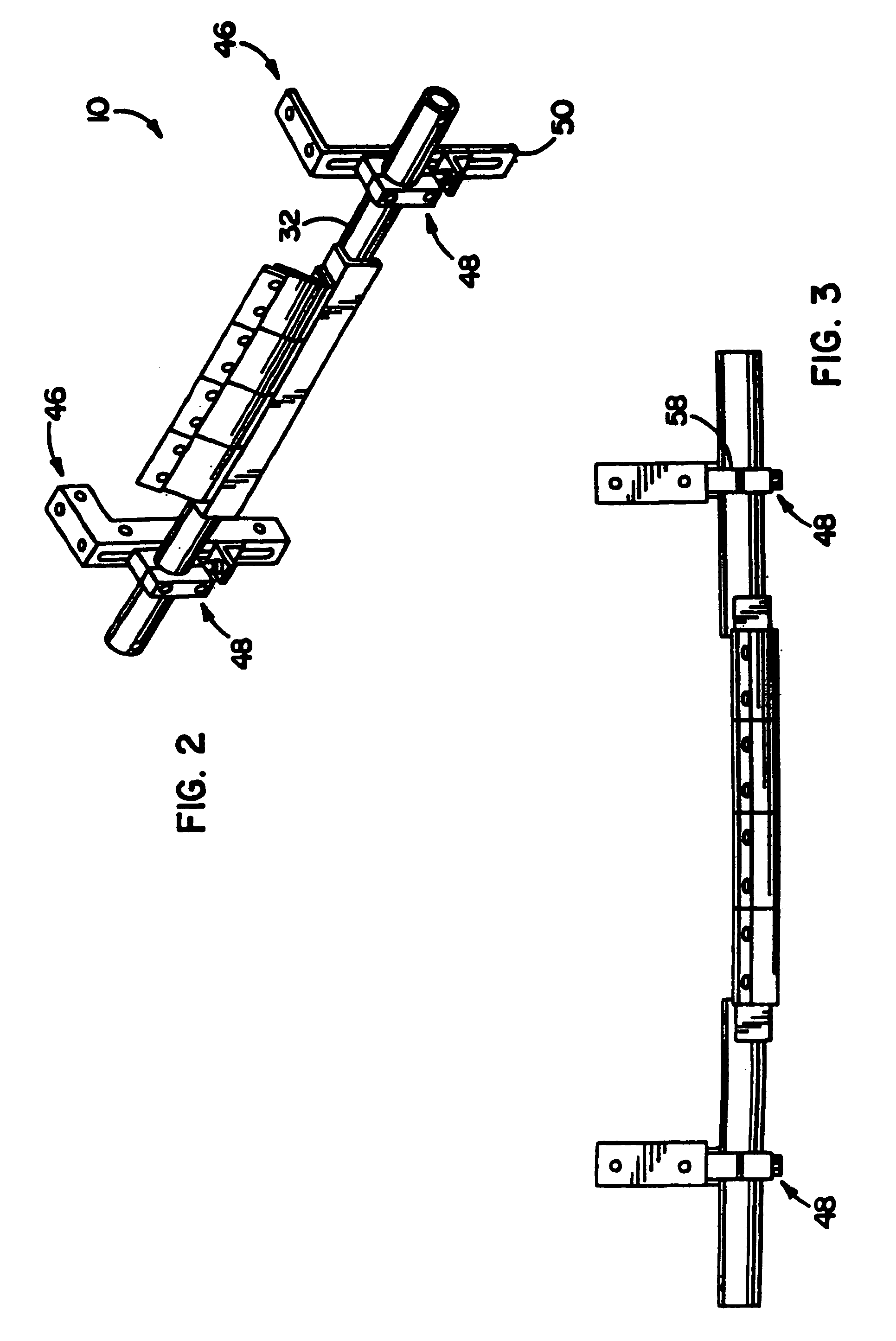
[0041]In FIG. 1, a cleaning assembly 10 for a conveyor belt 12 in accordance with the present invention is illustrated. The cleaning assembly 10 includes a belt cleaner having a scraper blade 14 that is attached to a blade mount member 16 which resiliently keeps the blade in engagement with the belt 12 as it is running. The blade mount member 16 is characterized by its ability to keep the blade 14 in substantially constant contact with the surface 12a of the conveyor belt 12 despite surface irregularities, i.e. deviations from a smooth, flat surface, that may be present thereon, while still allowing the blade 14 to resiliently shift away from the belt 12 when necessary to avoid taking the full brunt of high-impacts due to such surface irregularities. In this manner, the blade mount 16 is well-adapted to provide optimal cleaning efficiencies for the present cleaning assembly 10, and at the same time minimizes wear on the scraper blade 14 to increase the life thereof.

[0042]As can be s...


PUM


Abstract

A conveyor belt cleaner is provided that is particularly well-suited for high temperature applications. The cleaner includes a blade mount that has a layback arm mounting the cleaning blade and which can simultaneously deflect horizontally and vertically via changes in the radius of curvature of a lower arcuate portion connected thereto so as to minimize stress on the blade mount. The layback arm extends toward the conveyor belt at an acute layback angle relative to the immediately upstream belt surface. In another aspect, a belt cleaning system is provided including a plurality of resilient blade mounts that absorb the energy of impacts with the cleaning blade so as to allow for controlled release of the impact energy upon bringing the blade quickly back into scraping engagement with the belt. Preferably, two of these resilient mounts are associated with each blade in the belt scraping area and the others at ends of an elongate support laterally spaced from the scraping area.

Description

CROSS-REFERENCE TO RELATED APPLICATION[0001]This is a continuation-in-part of prior application Ser. No. 10 / 270,813, filed Oct. 15, 2002 now U.S. Pat. No. 6,823,983.FIELD OF THE INVENTION[0002]The invention relates to belt cleaning systems for conveyor belts and, more particularly, to resilient blade mounts for secondary belt cleaning systems.BACKGROUND OF THE INVENTION[0003]Cleaners for conveyors that utilize a scraping element to remove debris and other materials from conveyor belts are well known. These conveyor belts often include metallic splices extending across the belt that run past the scraper blades during conveyor belt operations. The scraper blades are typically biased into engagement with the belt to allow them to resiliently shift away from the belt when surface irregularities on the belt are encountered such as due to the aforementioned metallic splices.[0004]Generally, the goal of keeping the scraper blade in substantially constant contact with the belt to improve cl...

Claims


Application Information

Patent Timeline
Patent Type & Authority Patents(United States)
IPC IPC(8): B65G45/00B65G45/16
CPCB65G45/16
Inventor DEVRIES, BRETT EDWINWINKELMAN, JOHN H.WALDE, MARK L.
Owner FLEXIBLE STEEL LACING
Why Eureka
Try Eureka