Clamp holder

a technology of clamping and hose, which is applied in the direction of snapping fasteners, hose connections, machine supports, etc., can solve the problems of low working efficiency, inability to insert the hose, and useless effort to have to affix the positioning mark of the clamping on the hose, etc., to achieve the effect of facilitating the sub-assembly of the hose clamping

Inactive Publication Date: 2006-08-22
SUMITOMO RIKO CO LTD
View PDF16 Cites 19 Cited by
  • Summary
  • Abstract
  • Description
  • Claims
  • Application Information

AI Technical Summary

Benefits of technology

[0015]It is an object of this invention to facilitate the sub-assembly of a hose clamp as required for its preliminary fixing in position on a hose. It is another object of this invention to ensure that a hose clamp in a form of sub-assembl

Problems solved by technology

This method has, however, been low in working efficiency, since it necessitates the steps of moving the hose clamp and positioning it accurately in a busy pipe joining process.
It has also been a useless effort to have to affix a clamp positioning mark on the hose for the accurate positioning of the hose clamp.
The problem is that the ring-shaped arms 5 are somewhat smaller in diameter than the hose

Method used


Image

  • Clamp holder
  • Clamp holder
  • Clamp holder

Examples


embodiments

(Clamp Holder)

[0069]A clamp holder according to a preferred embodiment of this invention will now be described with reference to FIGS. 9 to 11C. The technical scope of this invention is, however, not limited by this embodiment.

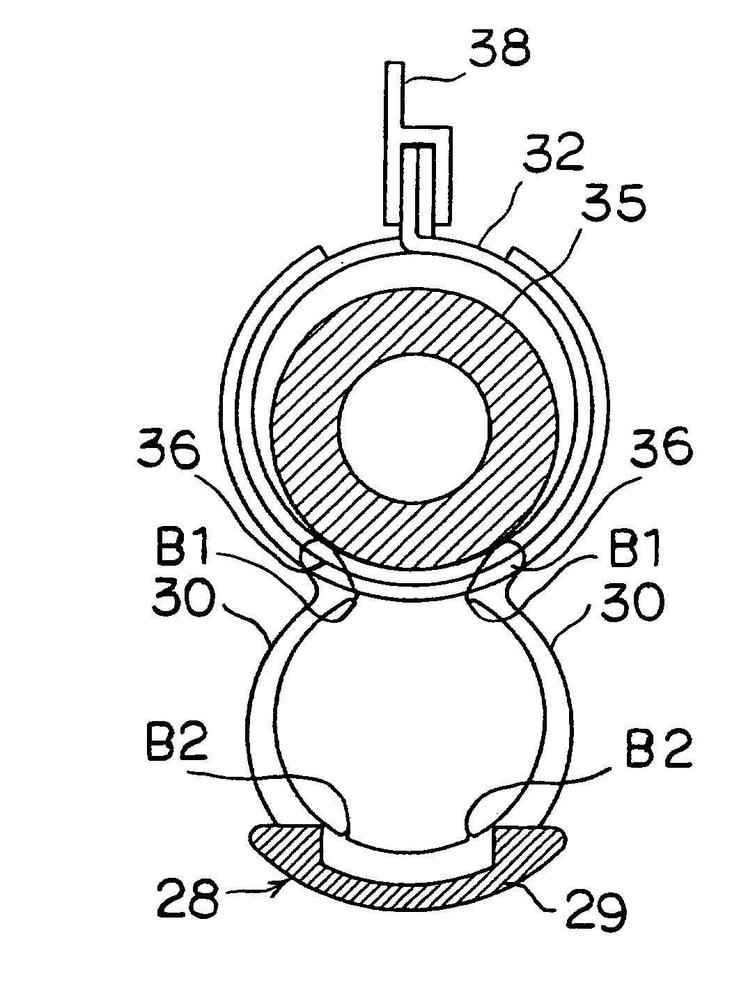
[0070]The clamp holder 28 shown in FIG. 9 is an integrally molded product of a plastic material. The clamp holder 28 has a holder base 29 in the form of a curved plate and a total of four holding arms 30 protruding from a pair of opposite edges of the holder base 29. The holder base 29 has an inner curved surface 31 so shaped as to engage intimately with the outer periphery of a diametrically expanded hose clamp 32, as shown in FIG. 11B. Moreover, the curved surface 31 has two appropriately situated positioning projections 33 that can engage in the slots or holes (not shown) of the hose clamp 32.

[0071]The holding arms 30 protrude from a base formed by an arm support portion 34 extending to some extent from each of a pair of lateral (or axially spaced) edges of...


PUM

PropertyMeasurementUnit
Angleaaaaaaaaaa
Angleaaaaaaaaaa
Thicknessaaaaaaaaaa

Abstract

In a holder having a holder base and holding arms and used for holding a hose clamp in position, the holder base is so constructed as to be capable of being positioned on the outer periphery of an annular hose clamp and a pair of holding arms protrude from each of a pair of opposite lateral edges of the holder base. Each pair of holding arms are so shaped as to define a pair of opposed arcs extending along a circumference A having a diameter somewhat smaller than the outside diameter of a hose. Each holding arm has a sharp projection B1 formed on its inner peripheral surface at its distal end and directed substantially toward the center of the circumference A, or more inwardly than it. The clamp holder facilitates the preliminary holding of a hose clamp in position on a hose without damaging the hose, and without slipping off the hose or being displaced easily.

Description

BACKGROUND OF THE INVENTION[0001]1. Field of the Invention[0002]This invention relates to a clamp holder. More particularly, this invention relates to a clamp holder for the preliminary fixing of a diametrically expanded hose clamp on a hose portion expected to be clamped at its joint with a pipe.[0003]2. Description of the Related Art[0004]It has hitherto been usual to carry out a pipe joining process for joining a rubber hose, etc. to a hard pipe and fixing their joint tightly with a hose clamp, as will be described below by way of example. A hose clamp 2 held in a diametrically expanded form by a stopper pin, etc. is fitted about a pipe 1 beforehand, as shown in FIG. 1A. Then, a hose 3 is joined with the pipe 1, and the hose clamp 2 is moved and positioned about their joint, as shown in FIG. 1B. Then, the hose clamp 2 is released from its diametrically expanded form to fix the joint tightly at a selected point. This method has, however, been low in working efficiency, since it ne...

Claims


Application Information

Patent Timeline
IPC IPC(8): E21F17/02F16L33/02F16L33/03
CPCF16L33/03Y10T24/1457Y10T24/1418
Inventor YUZURIHA, CHIAKIMORI, HIROYOSHI
Owner SUMITOMO RIKO CO LTD
Why Eureka
Try Eureka