
Antenna assembly

a technology of antenna assembly and antenna assembly, which is applied in the direction of resonant antennas, elongated active element feeds, and independent non-interacting antenna combinations. it can solve the problems of inapplicability, general individual cost, and limited system described by ali et al., and achieves the effect of low cost and easy connection

Inactive Publication Date: 2006-08-22
HEWLETT PACKARD DEV CO LP
View PDF18 Cites 12 Cited by
  • Summary
  • Abstract
  • Description
  • Claims
  • Application Information

AI Technical Summary

Benefits of technology

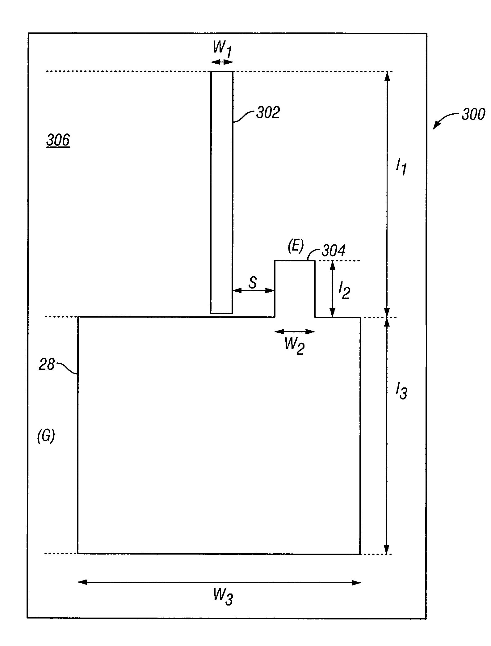
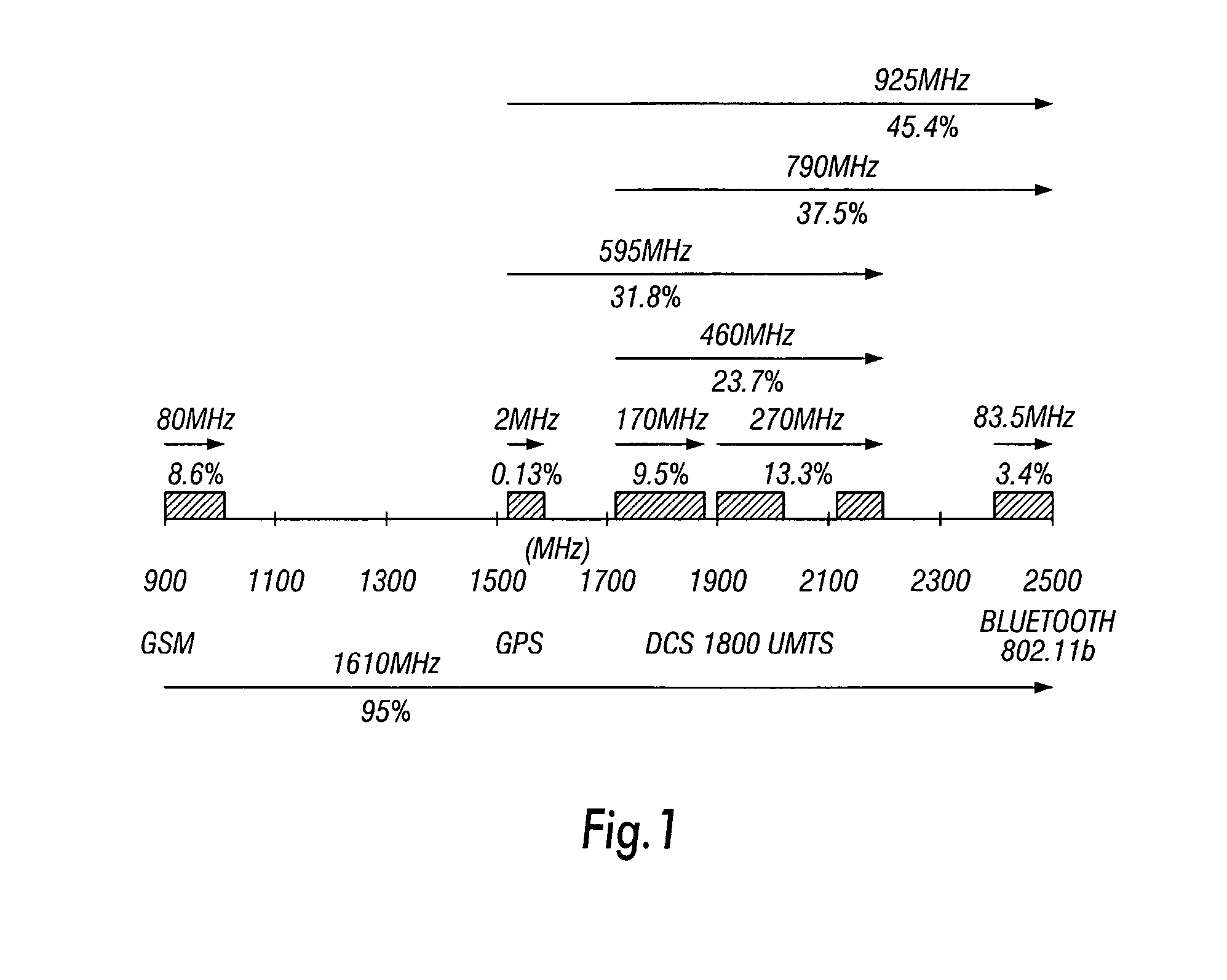
The present invention provides an improved antenna assembly for multi-band wireless communication. The assembly includes a monopole element and at least one grounded parasitic element located proximate to the monopole element. The monopole element is fed by a conducting member located on a substrate. The conductive member may be a conductive patch or a feed connector. The grounded element is substantially rectangular and extends parallel to the monopole element. The antenna assembly can communicate through a wide band, typically from 900 MHz to 2,500 MHz, and can scan all existing communication bands. It is small enough to be embedded into a portable computing device and can be easily connected as an attachment to the device. Only one single transmitter would transmit data at any given time. The antenna assembly is arranged to connect permanently to the band most used by the mobile computing device and to scan the other bands.

Problems solved by technology

The system described by Ali et al is however limited to dual frequency applications over a fairly narrow range of frequencies.
Although several antenna solutions already exist in the market for the different wireless communication standards described below, they are generally individually expensive, particularly if it is desired to provide a plurality of antennae to be able to scan all of the communication bands which are accessible.
These solutions are therefore not practicable and may further suffer from the drawback that when located in the same device, each may interfere with the others operation.

Method used


Image

  • Antenna assembly
  • Antenna assembly
  • Antenna assembly

Examples


Embodiment Construction

Preliminary Considerations

[0041]For a better understanding of the features and parameters of the described embodiments of the invention, the following detailed explanation of the problems and issues to overcome is as follows.

[0042]The specific embodiments of the invention described herein provide general purpose metallic strip-based antennae or antenna assemblies which are able to cover all (or at least a large proportion of) the wireless services which are presently available or expected to be used in Europe or USA in the foreseeable future.

[0043]The embodiments described herein are designed to be capable of covering the following wireless communication systems and frequencies for:[0044]GSM 900 / 1800 (GSM 1900 also for cases where UMTS compatibility is not required or when the compatibility problems with UMTS are resolved);[0045]IMT-2000 bands in all possible modes but more specifically oriented to UMTS; and[0046]ISM band wireless services such as Bluetooth or IEEE 802.11b.

[0047]Add...


PUM


Abstract

An antenna assembly is designed to operate over a wide band from around 880 MHz to around 2,500 MHz by means of a monopole antenna element designed to operate from around 880 MHz to around 2,500 MHz typically from the GSM bands to the Bluetooth or IEEE 802.11b band. The operation band width of the assembly is increased by the provision of a conductive member located on a reverse side of the supporting substrate of the antenna. In one embodiment the conductive member is a standard panel mount SMA connector. The assembly is able to provide wireless operation in multiple frequency bands, not previously possible in a practical manner.

Description

CROSS REFERENCE TO RELATED APPLICATIONS[0001]The subject matter of the present application may also be related to the following U.S. Patent Applications: “Dual-Access Monopole Antenna Assembly,” Ser. No. 10 / 825,093, filed Apr. 14, 2004; and “Single-Mode Antenna Assembly,” Ser. No. 10 / 825,094, filed Apr. 14, 2004.FIELD OF THE INVENTION[0002]The present invention relates to multiple-access antenna assemblies. More particularly, although not exclusively, the invention relates to strip-based antenna designs which are particularly suitable for simultaneous scanning of a frequency spectrum composed of multiple service sub-bands. The antennas of the present invention are particularly suitable for, although not limited to, use in portable or mobile devices where access is required to services such as wireless LANs, GPS and the like.BACKGROUND OF THE INVENTION[0003]With the rapid increase in wireless communication, there is an increasing need for mobile devices, such as portable computers, l...

Claims


Application Information

Patent Timeline
Patent Type & Authority Patents(United States)
IPC IPC(8): H01Q1/38H01Q1/24H01Q5/00H01Q5/357H01Q5/378H01Q5/385H01Q9/16H01Q9/30H01Q9/38H01Q9/40H01Q21/28
CPCH01Q9/16H01Q9/30H01Q9/38H01Q5/385H01Q21/28H01Q5/357H01Q5/378H01Q9/40
Inventor MONEBHURRUN, VIKASSAZOULAY, ALAINJOUVIE, FRANCOISMICHELET, JACQUES
Owner HEWLETT PACKARD DEV CO LP
Learn More