Fluorescent inspection of airfoil cooling holes

Active Publication Date: 2006-08-22
GENERAL ELECTRIC CO
View PDF5 Cites 6 Cited by
  • Summary
  • Abstract
  • Description
  • Claims
  • Application Information

AI Technical Summary

Benefits of technology

[0005]The present invention proposes a fluorescent inspection method that is both easier and more efficient to apply than existing methods of detecting no

Problems solved by technology

With the incorporation of laser drill methods that do not require the use of beam blocking wax, manufacturing has become more limited by manual pin-check.
Manual insertion of pin wires into 100% of the cooling holes on 100%

Method used


Image

  • Fluorescent inspection of airfoil cooling holes
  • Fluorescent inspection of airfoil cooling holes
  • Fluorescent inspection of airfoil cooling holes

Examples


Example

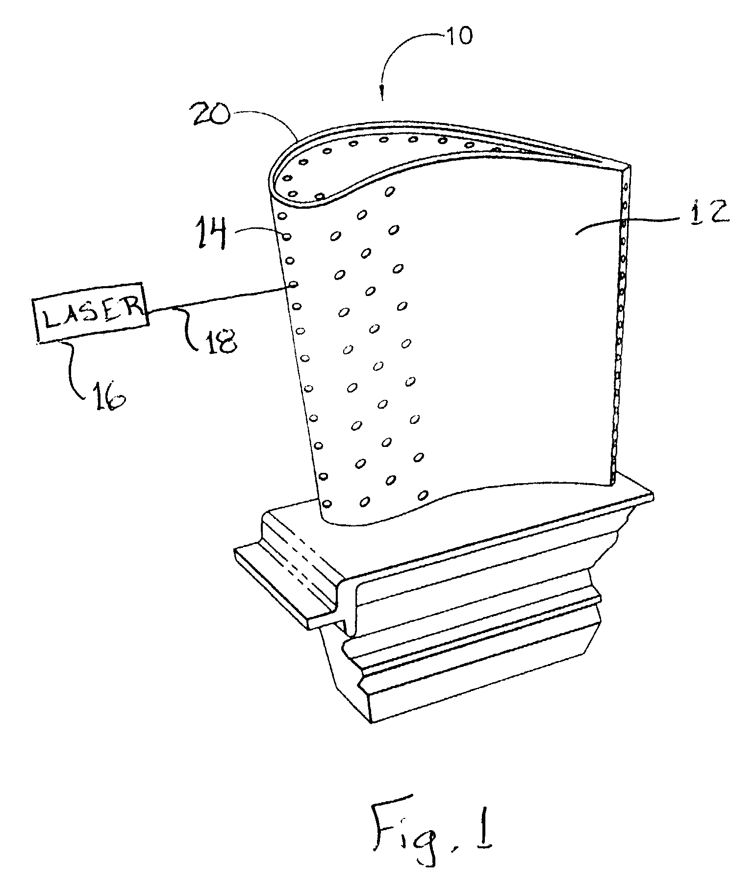
[0011]Referring to FIG. 1, there is illustrated a gas turbine engine blade 10 and airfoil 12 having a multiplicity of cooling channels or holes 14 formed therein by laser drilling to permit cooling of the blade during engine operation. The laser drilling to form the cooling holes 14 may be accomplished by any known method, such as by using a laser 16 and a laser beam 18 to drill the holes 14 in the wall 20, through to the hollow interior of the blade 10.

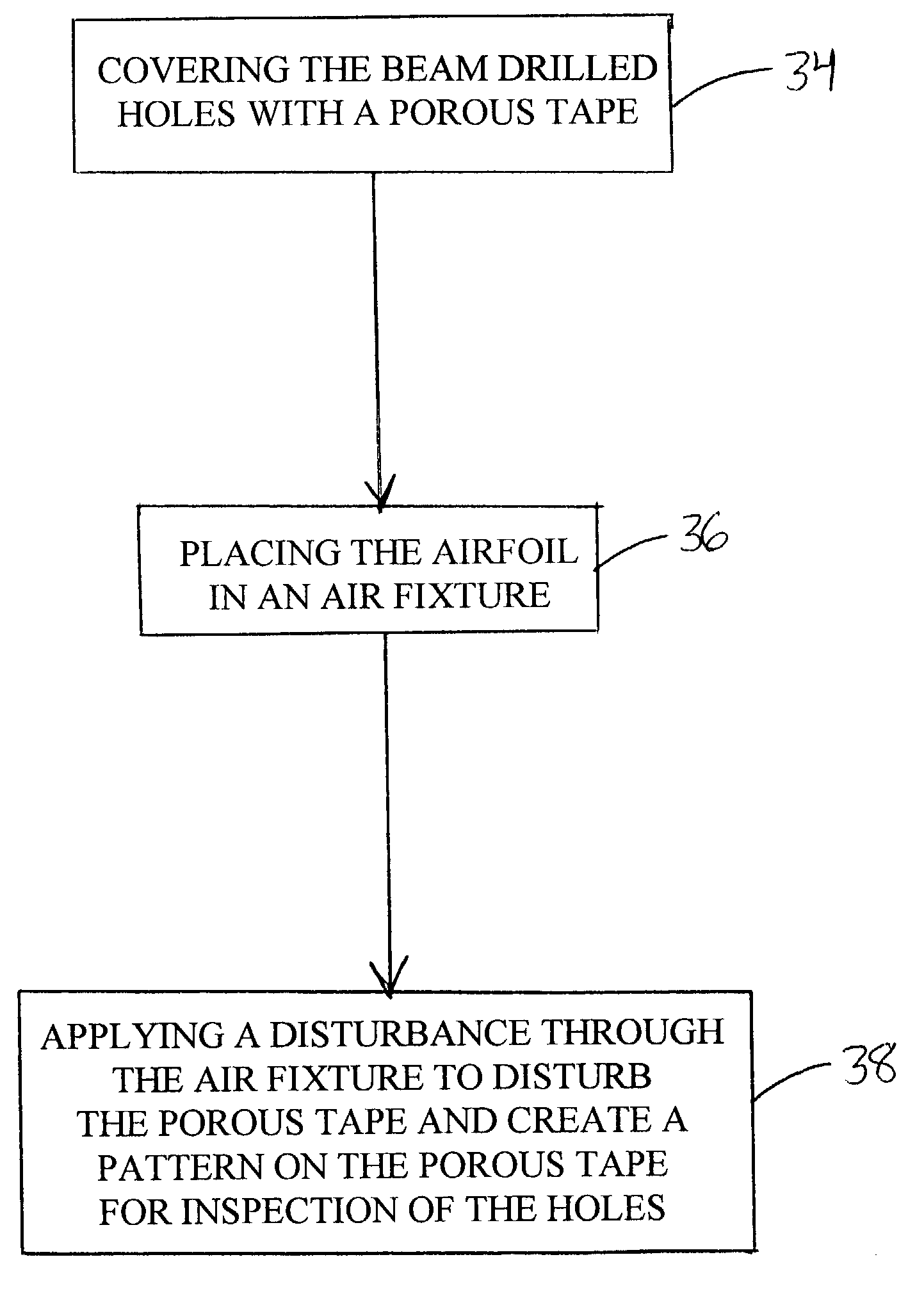
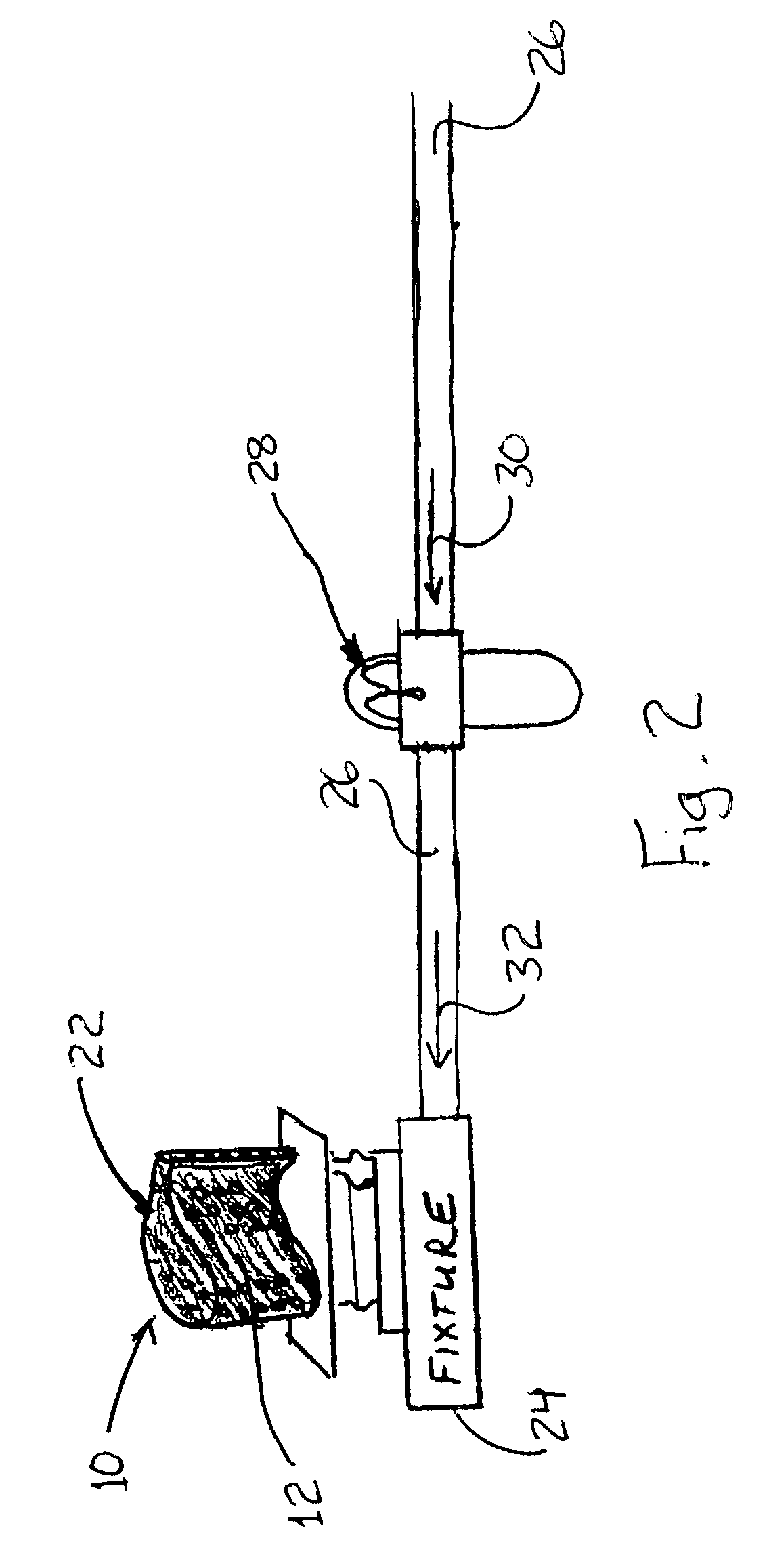
[0012]As illustrated in FIG. 2, a method is provided to inspect the cooling holes 14 to determine if the holes are open to the internal cavity of the blade 10. The holes are inspected to identify not-through or plugged holes. Referring to FIGS. 2 and 3, the cooling holes 14 of a completed, lasered and deburred turbine airfoil 10 are covered with a very porous tape 22, as indicated by step 34 of FIG. 3. The tape may be any suitable porous tape, such as, for example, 3M Vent tape #3394. The turbine airfoil 12 is then placed into an air...


PUM

PropertyMeasurementUnit
Areaaaaaaaaaaa
Fluorescenceaaaaaaaaaa

Abstract

A system and method are provided for inspecting cooling holes of a completed, lasered, and deburred turbine airfoil. The cooling holes are covered with a very porous tape before placing the turbine airfoil into an air fixture that has a metered amount of fluorescent liquid dripped into the airline. The atomized fluorescent liquid flows through the turbine airfoil internal cavities, exiting through the open cooling holes, where it is absorbed by the porous tape. A pattern will appear on the tape surface, in the area of the open holes, indicative of the presence of not-through or plugged cooling holes.

Description

BACKGROUND OF THE INVENTION[0001]The present invention relates to gas turbine engines, and, more specifically, to turbine airfoils.[0002]In the manufacture of turbine airfoils, it is often necessary to drill cooling holes through the outer airfoil walls entering the internal air passages. These holes provide a source of cooling air to the airfoil surface during engine operation. Several techniques, such as laser beam drilling, electro-discharge machining, or electro-steam drilling, are used to drill turbine airfoil cooling holes. After the drilling process, the cooling holes must be inspected to determine if they are open to the internal cavities. Methods used to inspect for holes that are not properly drilled through or are plugged include pin-check, by inserting a pin wire into the cooling holes; waterflow inspection; and black light inspection using a beam blocking wax and a fluorescent penetrant mixture.[0003]With the incorporation of laser drill methods that do not require the ...

Claims


Application Information

Patent Timeline
IPC IPC(8): G01N21/00B23K26/00G01N21/64G01N21/894G01N21/91
CPCG01N21/6447G01N21/95692G01N2021/646G01N21/91
Inventor BOWLES, GAYLE M.WHEAT, GARY E.SHEYER, WILLIAM L.
Owner GENERAL ELECTRIC CO
Why Eureka
Try Eureka