Optical disc device and control method using preceding sub-beam to detect a disc defect

a control method and optical disc technology, applied in the direction of digital signal error detection/correction, instruments, recording signal processing, etc., can solve the problems of over-described conventional methods, reduced data transfer rate, and complex overall construction, so as to effectively avoid a reduction of data transfer rate and high reliability

Inactive Publication Date: 2006-08-22
SONY CORP
View PDF16 Cites 20 Cited by
  • Summary
  • Abstract
  • Description
  • Claims
  • Application Information

AI Technical Summary

Benefits of technology

[0010]In view of the state of the art set forth above, it is an object of the present invention to provide an optical disc device and a control method for the optical disc device, which can confirm with a simple construction whether data is correctively reproduced, while effectively avoiding a reduction of the data transfer rate.
[0013]According to a second aspect of the present invention, there is provided a control method for an optical disc device in which a main beam spot and sub-beam spots are formed on an information recording surface of an optical disc with irradiation of a laser beam, and laser power of the laser beam is intermittently boosted to record desired data on the optical disc by the main beam spot, the method comprising the steps of suppressing changes in signal level of a light detection result caused upon boosting of the laser power of the laser beam, the light detection result being obtained by receiving a return light corresponding to one of the sub-beam spots, which is formed on preceding side with respect to scan of the main beam spot; and determining the light detection result and detecting the presence of defects on the optical disc.
[0017]According to the first aspect of the present invention, the optical disc device comprises the light receiving unit for receiving a return light corresponding to one of the sub-beam spots, which is formed on preceding side with respect to scan of the main beam spot, and outputting a light detection result, and the determining unit for determining the light detection result and detecting the presence of defects on the optical disc. Therefore, the state of the information recording surface can be determined for an area, which is just going to be scanned by the main beam spot, by using the sub-beam spot for tracking control while data is recorded by the main beam spot. Also, since the optical disc device further comprises the correcting unit for suppressing changes in signal level of the light detection result caused upon boosting of the laser power of the laser beam, the state of the information recording surface can be determined with high reliability by avoiding an adverse effect of changes in laser power of the laser beam caused upon recording of the data. As a result, it is possible to confirm with a simple construction, while effectively avoiding a reduction of the data transfer rate.
[0018]According to the second aspect of the present invention, the control method for the optical disc device is provided which can confirm with a simple construction whether data is correctively reproduced, while effectively avoiding a reduction of the data transfer rate.
[0019]According to the third aspect of the present invention, the optical disc device comprises the light receiving unit for receiving a return light corresponding to one of the sub-beam spots, which is formed on succeeding side with respect to scan of the main beam spot, and outputting a light detection result, and the determining unit for processing the light detection result and determining an error in the data recorded on the optical disc by the main beam spot and an error in address data obtained from the optical disc. Therefore, whether the recorded data and address data can be correctly reproduced can be determined for an area, which is in a state immediately after being scanned by the main beam spot, by using the sub-beam spot for tracking control while data is recorded by the main beam spot. Also, since the optical disc device further comprises the correcting unit for suppressing changes in signal level of the light detection result caused upon boosting of the laser power of the laser beam, whether the recorded data and the address data can be correctly reproduced can be determined with high reliability by avoiding an adverse effect of changes in laser power of the laser beam caused upon recording of the data. As a result, it is possible to confirm with a simple construction whether data can be correctly reproduced, while effectively avoiding a reduction of the data transfer rate.
[0020]According to the fourth aspect of the present invention, the control method for the optical disc device is provided which can confirm with a simple construction whether data is correctively reproduced, while effectively avoiding a reduction of the data transfer rate.

Problems solved by technology

However, the above-described conventional methods have problems as follows.
On the other hand, with the method employing the recording pickup and the reproducing pickup, a reduction of the data transfer rate can be effectively avoided, but the overall construction becomes complicated because of the necessity of arranging the two optical pickups.
Further, with the method providing the defect detecting mechanism on the optical pickup, a reduction of the data transfer rate can also be effectively avoided, but the optical pickup has a complicated construction and the overall construction becomes complicated correspondingly.

Method used


Image

  • Optical disc device and control method using preceding sub-beam to detect a disc defect
  • Optical disc device and control method using preceding sub-beam to detect a disc defect
  • Optical disc device and control method using preceding sub-beam to detect a disc defect

Examples


first embodiment

(1-2) Operation of First Embodiment

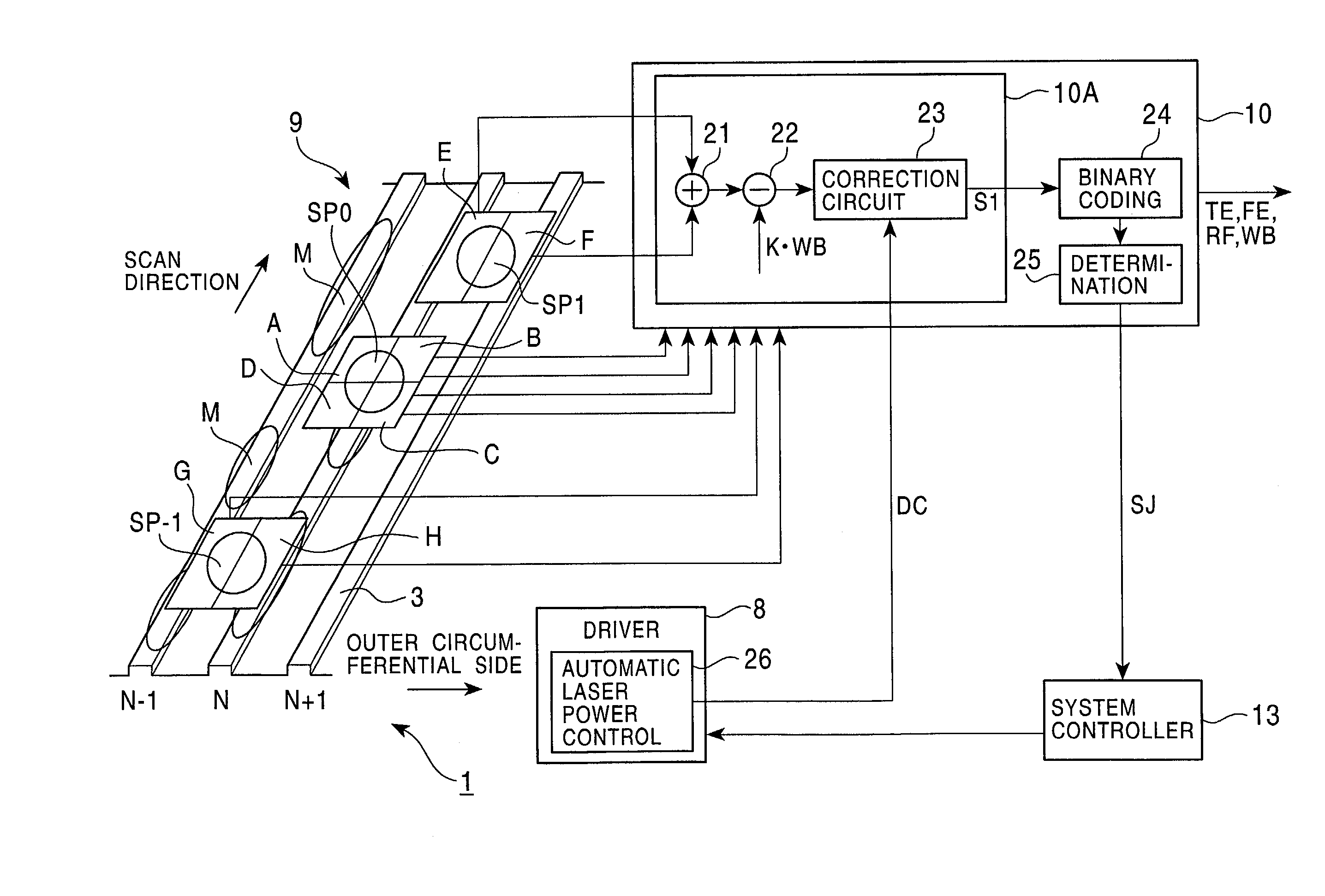
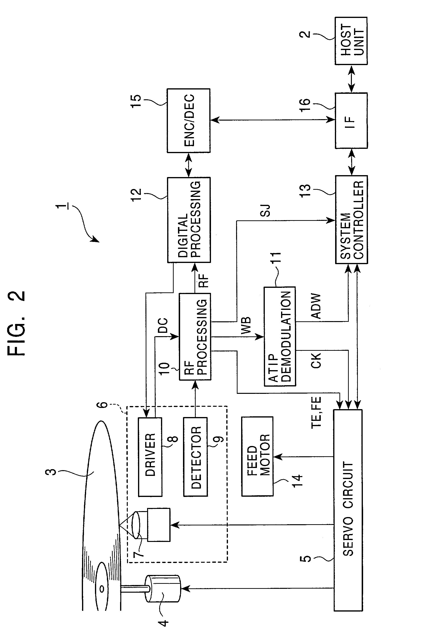
[0060]In the construction described above, when reproduction of data from the optical disc 3 is instructed from the host unit 2 in the optical disc device 1 (FIG. 2), the result of detecting the return light obtained by irradiating the laser beam to the optical disc 3 from the optical pickup 6 is processed by the RF processing circuit 10 to generate the reproduction signal RF whose signal level varies depending on the pit rows or the mark rows formed in or on the optical disc 3. Then, the reproduction signal RF is processed by the digital processing circuit 12 to generate reproduction data, and the encoder / decoder 15 processes the reproduction data. As a result, the data recorded on the optical disc 3 is reproduced. The data thus reproduced in the optical disc device 1 is outputted to the host unit 2 via the interface 16.

[0061]On the other hand, when recording of data on the optical disc 3 is instructed from the host unit 2, data to be recorded is ...

second embodiment

(2) Second Embodiment

[0074]FIG. 5 is a block diagram showing, in comparison with FIG. 1, an optical disc device according to a second embodiment of the present invention. In an optical disc device 31 of this embodiment, the sub-beam spots SP-1, SP1 are formed by respective side beams in arrangement reversed to that in the first embodiment with respect to the radial direction of the optical disc 3, and an RF processing circuit 32 is employed instead of the RF processing circuit 10 described above in connection with the first embodiment. Except for those points, the optical disc device 31 of this embodiment has the same construction as optical disc device 1 of the first embodiment. Note that, in the construction shown in FIG. 5, the same points as those in the first embodiment are not described here.

[0075]In this embodiment, the sub-beam spot SP-1 formed by the diffracted light of −1 order is formed on the preceding side with respect to the main beam spot SP0 as viewed in the radial d...

third embodiment

(3) Third Embodiment

[0080]In this embodiment, instead of controlling the laser power of the laser beam based on the determination result SJ, data is rerecorded in a succeeding area with the so-called slipping process while writing is temporarily suspended. To that end, the system controller processes the management information, which is recorded on the inner circumferential side of the optical disc 3, corresponding to the slipping process.

[0081]The temporary suspension of writing means suspension of writing of data to be recorded, and hence includes not only the case in which neither pit row nor mark row is formed by actually stopping the operation of boosting the laser power of the laser beam, but also the case in which dummy data is recorded instead of the data to be recorded. Note that determination as to the presence of defects is executed in the same manner as in the first or second embodiment.

[0082]Similar advantages to those in the above-described embodiments can also be obta...


PUM

PropertyMeasurementUnit
diameteraaaaaaaaaa
diameteraaaaaaaaaa
diameteraaaaaaaaaa

Abstract

The invention relates to an optical disc device and a control method for the optical disc device. The presence of defects on an optical disc is confirmed by, based on the result of detecting a return light corresponding to a sub-beam spot used for tracking control, which is formed on the preceding side with respect to scan of a main beam spot, suppressing changes in signal level of the light detection result caused upon boosting of the laser power of a laser beam. Also, whether data can be correctly reproduced is determined by, based on the result of detecting a return light corresponding to a sub-beam spot used for tracking control, which is formed on the succeeding side with respect to scan of the main beam spot, suppressing changes in signal level caused upon writing of the data. Therefore, whether data can be correctly reproduced can be confirmed with a simple construction while effectively avoiding a reduction of the data transfer rate.

Description

BACKGROUND OF THE INVENTION[0001]1. Field of the Invention[0002]The present invention relates to an optical disc device and a control method for the optical disc device, and is applicable to an optical disc device for recording and reproducing data on and from an optical disc, such as a CD-R. More particularly, the present invention intends to make it possible to confirm whether data can be correctly reproduced, with a simple construction while effectively avoiding a reduction of the data transfer rate, by suppressing changes in signal level caused upon boosting of the laser power of a laser beam and detecting the presence of defects on an optical disc based on the result of detecting a return light corresponding to a sub-beam spot used for tracking control, which is formed on the preceding side with respect to scan of a main beam spot used to form pits or marks for recording of the data. Also, the present invention intends to make it possible to confirm whether data can be correctl...

Claims


Application Information

Patent Timeline
Patent Type & Authority Patents(United States)
IPC IPC(8): G11B7/0045G11B7/125G11B7/0037G11B7/085
CPCG11B7/00375G11B7/0045G11B7/08517G11B7/004G11B7/09
Inventor SASAKI, TAKASHITAKASE, TSUNEMITSU
Owner SONY CORP
Why Eureka
Try Eureka