Catalytic combustion system and method

a catalytic combustion and combustion system technology, applied in the ignition of the turbine/propulsion engine, engine starters, lighting and heating apparatus, etc., can solve the problems of increased co emissions, increased co emissions, and catalytic systems that typically need more time to burn co, so as to reduce carbon monoxide emissions from the turbine engine and shorten the combustion flame length

Inactive Publication Date: 2006-08-29
SIEMENS ENERGY INC
View PDF41 Cites 36 Cited by
  • Summary
  • Abstract
  • Description
  • Claims
  • Application Information

AI Technical Summary

Benefits of technology

[0005]Thus, one object according to aspects of the present invention is to provide a catalytic combustion system that can reduce CO emissions. Another object according to aspects of the present invention is to provide a catalytic combustion system configured to shorten flame lengths. Still another object according to aspects of the invention is to provide a catalytic combustion system that allows for the tuning of the shape of the flame so as to optimize system performance. Yet another object according to aspects of the invention is to allow for the use of catalytic combustion systems in connection a variety of turbine combustor systems. These and other objects according to aspects of the present invention are addressed below.
[0011]At least one vortex is created in at least a portion of the catalytic flow stream. The at least one vortex in the catalytic flow stream causes at least a portion of the pilot flow stream to mix with at least a portion of the catalytic flow stream. Consequently, the hotter pilot flow stream accelerates the burnout reaction in the catalytic flow stream and further shortens the combustion flame length so as to reduce carbon monoxide emissions from the turbine engine.
[0015]An at least partially reacted pilot flow stream at a pilot temperature is provided. The pilot temperature is greater than the catalytic temperature. At least a portion of the pilot flow stream travels substantially adjacent to at least a portion of the catalytic flow stream. The catalytic and pilot flow streams remain substantially unmixed. Secondary motion is generated in at least a portion of the catalytic flow stream such that at least a portion of the catalytic flow stream mixes with at least a portion of the pilot flow stream. As a result, the hotter pilot flow stream accelerates the burnout reaction in the catalytic flow stream and further shortens the combustion flame length so as to reduce carbon monoxide emissions from the turbine engine.

Problems solved by technology

While successful in combating NOx emissions, catalytic combustors can result in higher CO output from the engine, even at desired operating points such as base load.
The higher CO emissions are also a symptom of the relatively cold temperatures at which catalytic combustion occurs.
Because the temperature of the catalytic combustion reaction is relatively low, catalytic systems typically need more time to burn the CO.
The longer burnout time in turn requires a combustion system having a sufficiently long travel path for the combustion gases to provide the requisite time for burnout before the gases leave the combustion system; however, due to packaging issues and economic feasibility, many engines cannot accommodate extra physical length.
Thus, burnout takes longer than the distance (and travel time) available.
The above problems can arise in almost any type of catalytic combustor system, including both lean and rich catalytic systems.

Method used


Image

  • Catalytic combustion system and method
  • Catalytic combustion system and method
  • Catalytic combustion system and method

Examples


Embodiment Construction

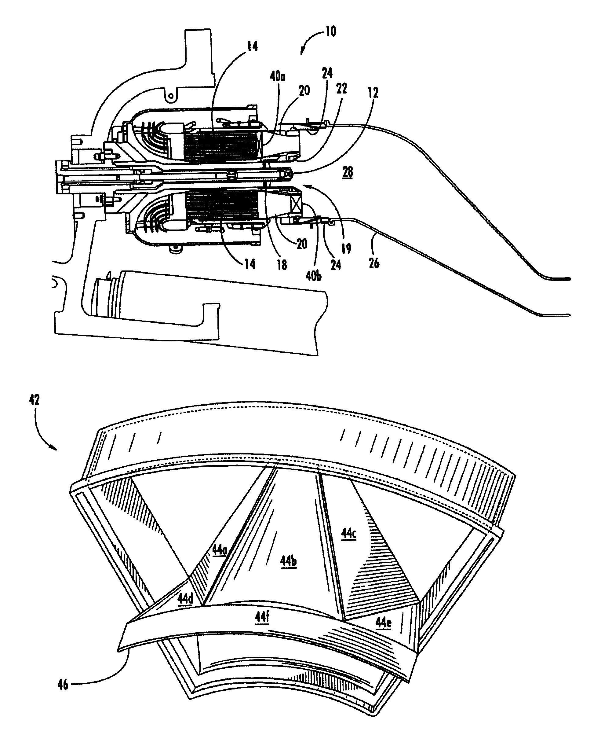
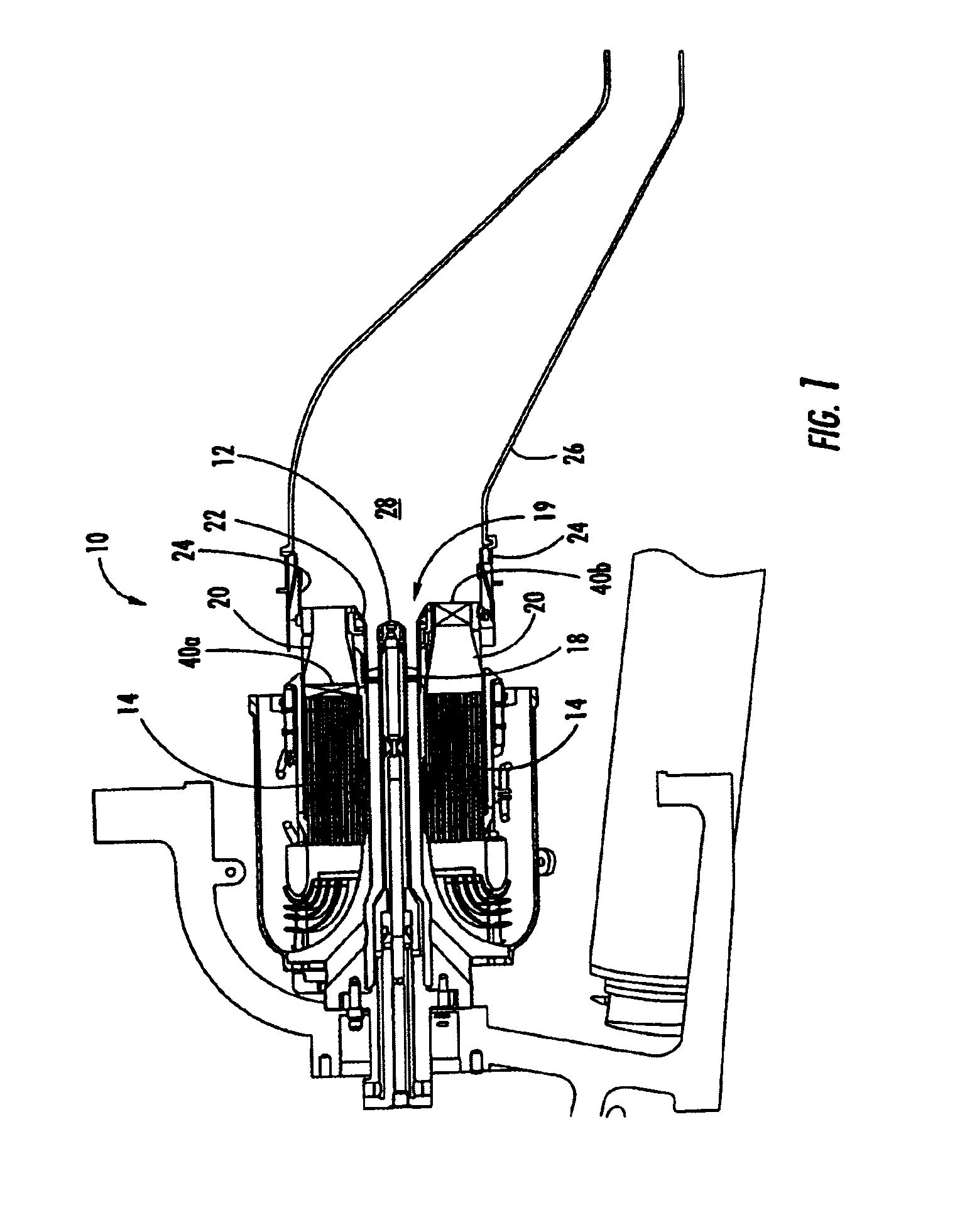
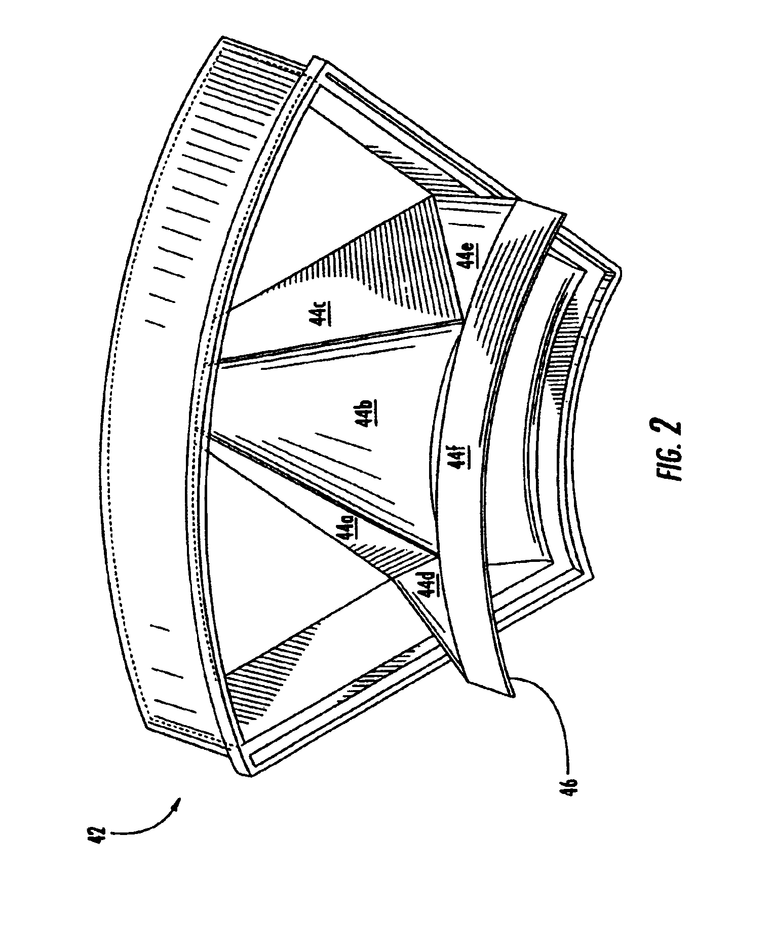
[0018]Aspects of the present invention relate to catalytic combustion systems and methods for reducing CO emissions in turbine engines having catalytic combustion systems. Embodiments according to aspects of the invention are shown in FIGS. 1–2, but the present invention is not limited to the illustrated structure or application. Further, the following detailed description is intended only as exemplary.

[0019]A catalytic turbine engine generally has a compressor section, a catalytic combustor section and a turbine section. One example of a catalytic combustor system 10 according to aspects of the invention is shown in FIG. 1. The basic configuration of the combustor 10 can include a pilot 12 peripherally surrounded by a plurality of catalytic modules 14. In one embodiment, there can be at least six catalytic modules 14 surrounding the pilot 12, which can have an associated nozzle 13. However, there are many alternative combustor configurations. For example, a pilot can be peripherall...


PUM


Abstract

Aspects according to the invention relate to a catalytic combustor system for a turbine engine and an associated method. Catalytic combustors are used in connection with turbine engines because they can minimize the formation of oxides of nitrogen during combustion. Despite this emissions advantage, catalytic combustion systems can increase the level of CO in the turbine exhaust. According to aspects of the invention, vortex formation devices includes vortex generators, swirlers and mixers can be placed downstream of each catalytic module surrounding the pilot nozzle so as to form one or more vortices in the otherwise substantially laminar flow exiting the modules. The vortices can create a suction so that a portion of the flow exiting the pilot nozzles is mixed with the flow exiting the catalyst modules. The introduction of the higher temperature pilot flow can accelerate the catalytic reaction time, promoting burnout of the CO formed during combustion.

Description

FIELD OF THE INVENTION[0001]The invention relates in general to turbine engines and, more particularly, to turbine engines having catalytic combustion systems.BACKGROUND OF THE INVENTION[0002]Turbine engines can include a variety of systems to minimize undesired emissions, such as oxides of nitrogen (NOx) and carbon monoxide (CO), generated during combustion. For example, some turbine engines use catalytic combustors to reduce the generation of NOx because catalytic combustion occurs at temperatures well below the temperature necessary for NOx production (above about 2700 degrees Fahrenheit). Catalytic combustion can occur at temperatures up to about 1000 degrees Fahrenheit to about 1400 degrees Fahrenheit. In contrast, conventional combustion temperatures can range from about 2500 to about 2900 degrees Fahrenheit.[0003]While successful in combating NOx emissions, catalytic combustors can result in higher CO output from the engine, even at desired operating points such as base load....

Claims


Application Information

Patent Timeline
Patent Type & Authority Patents(United States)
IPC IPC(8): F02C7/22F02C7/26
CPCF23R3/40
Inventor BLAND, ROBERTBANDARU, RAMARAO V.BATTAGLIOLI, JOHN
Owner SIEMENS ENERGY INC
Why Eureka
Try Eureka