Anhydrous ammonia fertilizer flow control apparatus and method

a technology of flow control and ammonia fertilizer, which is applied in the direction of liquid fertiliser distribution, agriculture, planting, etc., can solve problems such as pressure loss

Active Publication Date: 2006-08-29
360 YIELD CENT
View PDF24 Cites 23 Cited by
  • Summary
  • Abstract
  • Description
  • Claims
  • Application Information

AI Technical Summary

Benefits of technology

[0010]The method and apparatus of the present invention supplies liquid anhydrous ammonia to a pump or other flow control system which is part of a system for application of agricultural ammonia fertilizer. This invention uses a gas separation chamber to remove vapor generated by friction in the flow path from a storage tank containing saturated anhydrous ammonia. Additionally, liquid ammonia in the separation chamber creates a static head pressure. The difference in height between the inlet near the top of the chamber and the outlet at the bottom causes the static head pressure differential. This static head assures pure liquid at the bottom since absolute pressure there exceeds saturation pressure. As a result, the liquid feed stream to the pump or other flow control system is free of ammonia vapor.
[0012]The gas separation chamber is composed of three sections. Past the feed entry is a quieting section which allows gaseous bubbles to rise out of the liquid stream. This section has a larger diameter to provide increased volume to reduce fluid velocity. Above the quieting section is head space for collection and separation of gaseous ammonia. This space has enough volume to allow liquid level to rise and fall as the gaseous ammonia is metered out of the chamber. Below the quieting section is a reduced diameter stand pipe which creates static head pressure additive to the inlet pressure. The smaller diameter of the stand pipe section reduces the amount of anhydrous liquid stored in the chamber. The diameter need only be big enough to prevent a significant loss of pressure due to fluid friction.

Problems solved by technology

As the liquid stream passes through valves, fittings and a connecting hose to the applicator system it experiences a pressure loss due to friction in the hose.

Method used


Image

  • Anhydrous ammonia fertilizer flow control apparatus and method
  • Anhydrous ammonia fertilizer flow control apparatus and method
  • Anhydrous ammonia fertilizer flow control apparatus and method

Examples


Embodiment Construction

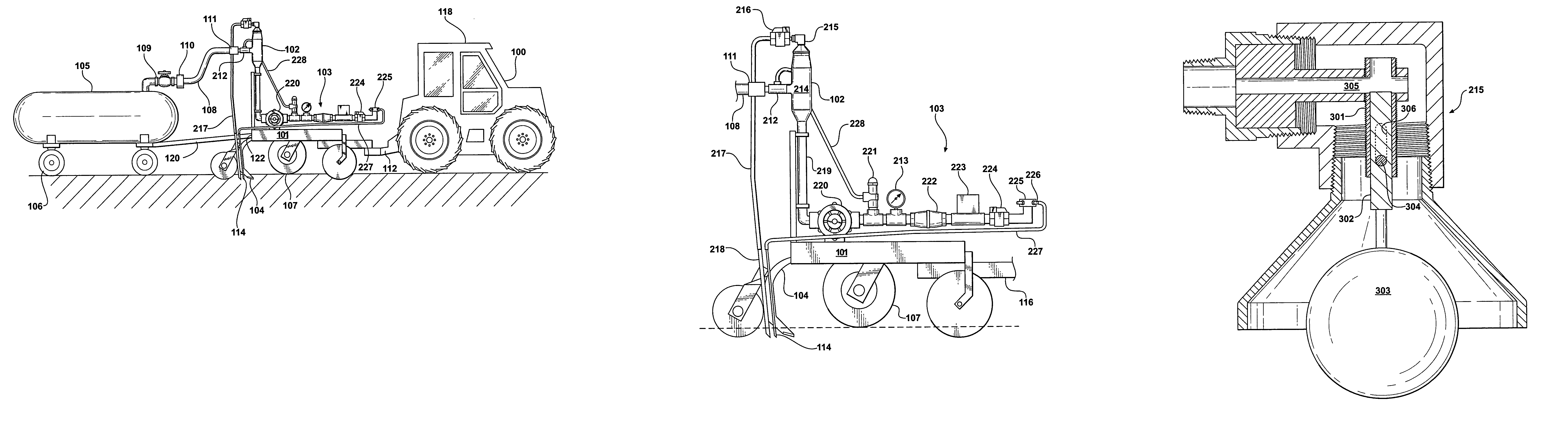
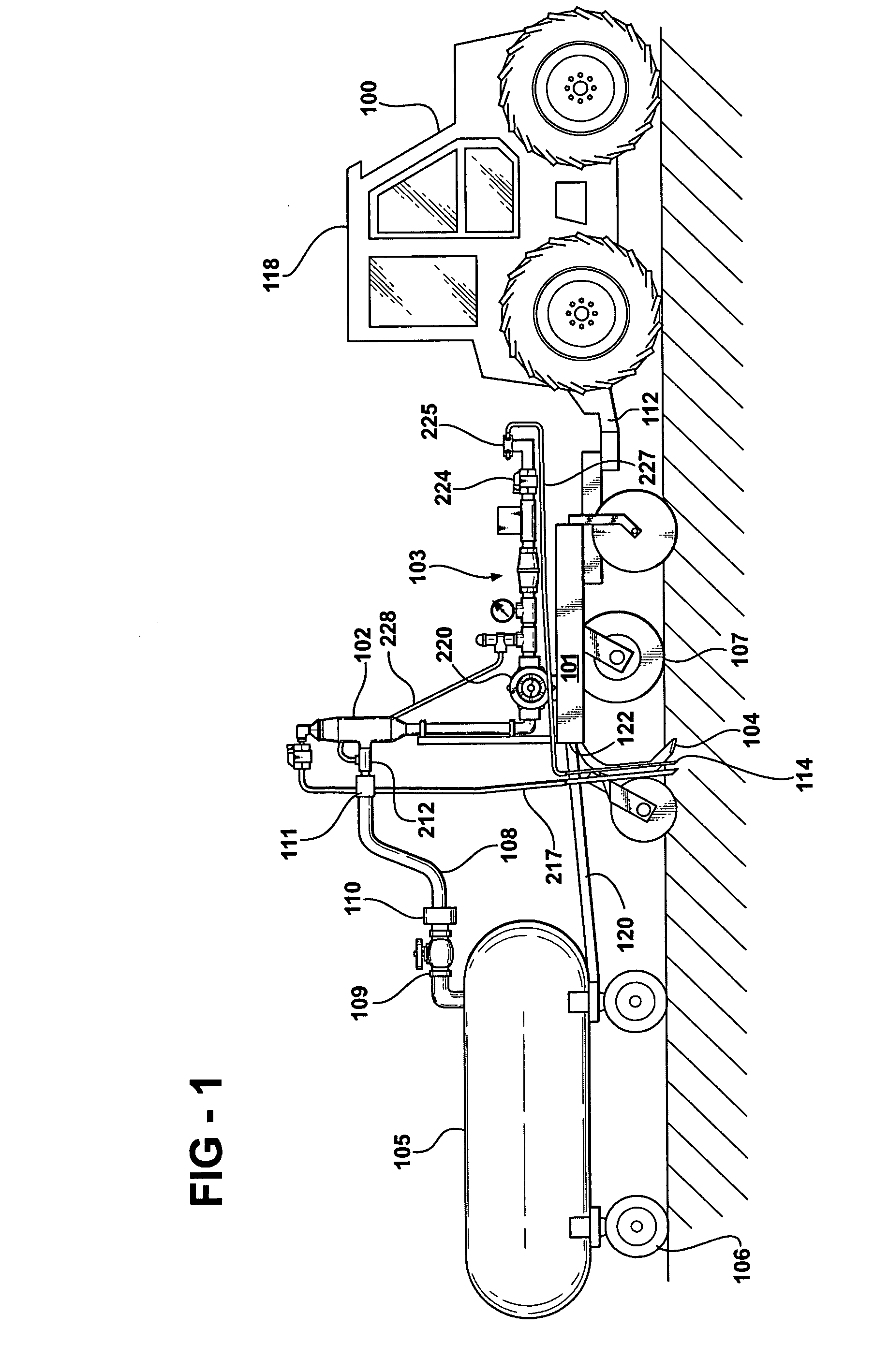
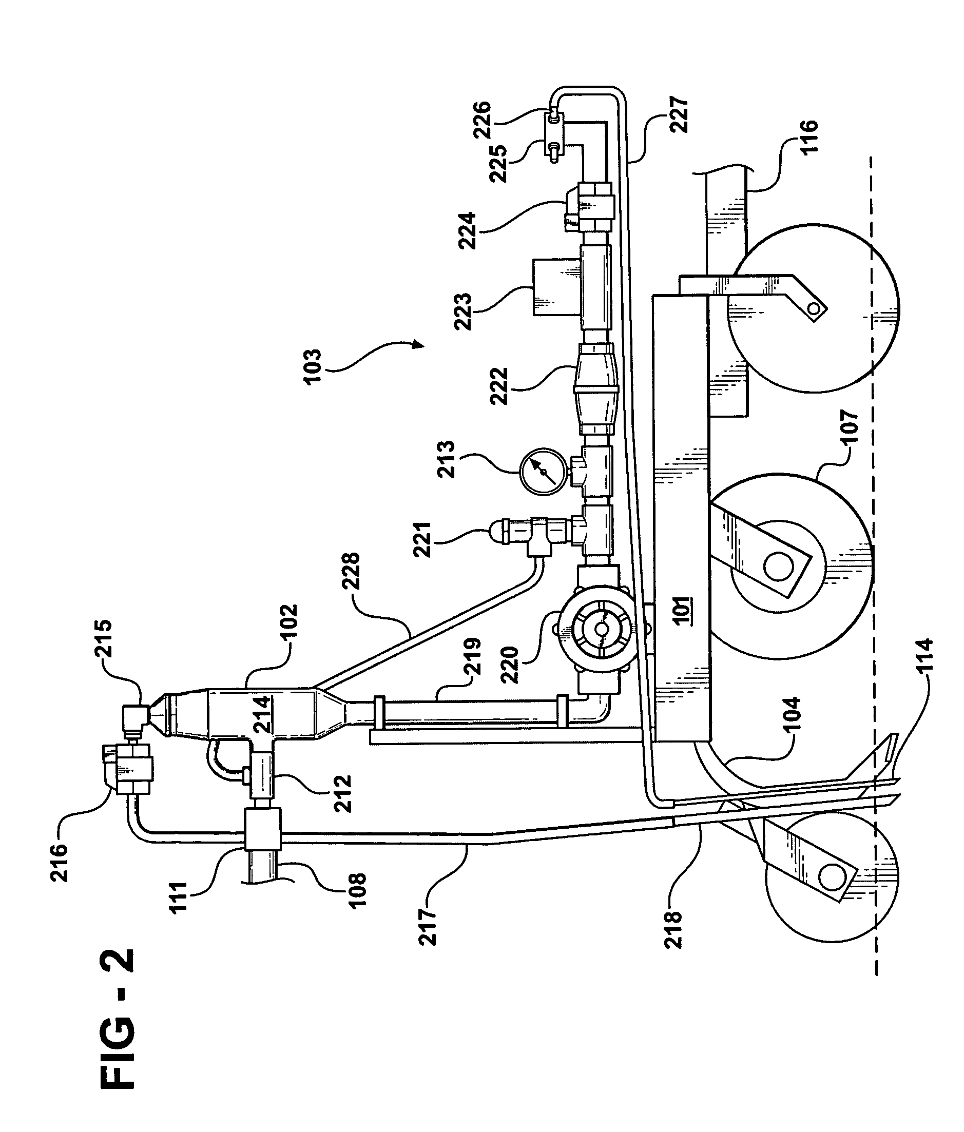
[0019]Referring first to FIG. 1, the apparatus of the present invention is shown being pulled behind a tow vehicle 100 which could be a tractor, truck, or the like. The apparatus includes a toolbar applicator frame 101 which supports a separation chamber 102, a flow control system 103 which may include a pump 220, a hydraulically operated shut off valve 224, a distribution manifold 225, flow control orifices 226, a plurality of soil cutting knives 104, and a storage tank 105 supported on a plurality of wheels 106 and towed behind the toolbar applicator frame 101. The toolbar applicator frame 101 itself is supported on a plurality of wheels 107 and has a tongue 116 that is pivotally connected to a hitch 112 on the rear of the tow vehicle 100. In the preferred embodiment, the toolbar applicator frame 101 is a Progressive series 1300 NH3 Toolbar, manufactured by Progressive Farm Products, Inc. of Hudson, Ill. It is configured by Progressive for “strip till” ammonia application. Multipl...


PUM


Abstract

A method and apparatus for supplying liquid anhydrous ammonia to a pump or other flow control system whereby a separation chamber removes vapor generated by friction in the flow path from a storage tank containing saturated anhydrous ammonia. Additionally, liquid ammonia in the separation chamber creates a static head pressure. The difference in height between the inlet near the top of the separation chamber and the outlet at the bottom causes the static head pressure. The static head assures pure liquid at the bottom since absolute pressure exceeds saturation pressure. As a result, the feed stream to the pump or other flow control system is free of ammonia vapor.

Description

CROSS REFERENCE TO RELATED APPLICATIONS[0001]This application claims the benefit of the filing date of U.S. Provisional Application No. 60 / 462,844, titled “Method and Apparatus for Supplying Liquid Anhydrous Ammonia To A Flow Control System,” filed Apr. 15, 2003.FIELD OF THE INVENTION[0002]The present invention relates to a new apparatus and method for providing vapor free liquid to an anhydrous ammonia flow control system. More particularly, the invention relates to a process which removes gaseous ammonia from the liquid stream and provides a static head pressure differential at the inlet of the flow control system. The static head causes anhydrous ammonia at the inlet to have an absolute pressure above its saturation pressure.BACKGROUND OF THE INVENTION[0003]Injection of anhydrous ammonia into the soil is a commonly used method of supplying nitrogen fertilizer to grain and other crops using an applicator-vehicle pulled by a tractor. An ammonia storage tank is pulled behind the app...

Claims


Application Information

Patent Timeline
Patent Type & Authority Patents(United States)
IPC IPC(8): A01C23/00
CPCA01C23/024Y10S111/925Y10S111/90
Inventor KIEST, LAUREN J.
Owner 360 YIELD CENT
Why Eureka
Try Eureka