
Bow mounted vessel propulsion system

a propulsion system and bow mounted technology, applied in marine propulsion, special-purpose vessels, vessel construction, etc., can solve the problems of reduced speed, adverse operations, and substantial surface drag along the hull of the vessel, so as to improve fuel efficiency and vessel speed, reduce the hull surface drag, and improve the maneuverability of the vessel.

Active Publication Date: 2006-08-29
ADAMS ROBERT D
View PDF8 Cites 21 Cited by
  • Summary
  • Abstract
  • Description
  • Claims
  • Application Information

AI Technical Summary

Benefits of technology

[0006]It is another object of the present invention to provide a bow mounted vessel propulsion system which reduces the hull surface drag, resulting in increased fuel efficiency and vessel speed.
[0007]It is still another object of the present invention to provide a bow mounted vessel propulsion system which will result in more efficient vessel maneuverability, since steering and propulsion means are combined at the bow section of the vessel, which is the leading edge of travel.
[0008]It is a further object of the present invention to provide a bow mounted vessel propulsion system which will result in safer conditions for vessels getting underway by virtually eliminating the bow-rise experienced in typical stern driven vessel configurations, as bow-rise (creating obscured or reduced forward visibility) is considered the primary cause of most recreational boating collisions.
[0009]It is an additional object of the present invention to provide a bow mounted vessel propulsion system which will result in safer conditions for water sports activities such as water skiing and wave boarding, since the danger of a rotating propeller is not in the proximity of the onboard and offboard activity.
[0010]It is still another object of the present invention to provide a bow mounted vessel propulsion system which will result in safer conditions during rescue maneuvers, landings and off-landings, again, since the danger of a rotating propeller is eliminated during these activities.
[0011]These and other objects are accomplished by the present invention, a bow mounted, vessel propulsion system designed to exploit the characteristics of a self-producing vessel lubricating boundary layer of air or air bubbles formed during water surface interaction by the vessel's hull during vessel movement. This boundary layer of air / air bubbles will be produced at the bow of the vessel and, during forward motion, is superimposed upon the surface of the water as the vessel's hull passes over, reducing the frictional drag of the hull as it moves across and through the water. The system has a propulsion means such as a water surface-piercing propeller or water jet nozzles, which will propel the vessel forward and, at the same time, by action of propeller rotation (drawing air into and intermixing) in the water or water jet movement, will create the air bubbles which produce the hull-lubricating phenomenon. The hull is a substantially flat-bottomed planning hull with two linear rails on each lengthwise outer edge of the bottom surface of the hull. The rails extend downward into the water at a sufficient depth to be able to keep the boundary layer of air bubbles from escaping out from the sides of the hull bottom when the vessel is in forward motion.

Problems solved by technology

However, such vessel movement, especially for high-speed conveyance, produces substantial surface drag along the hull of the vessel.
This results in adverse operations, including reduction of speed and loss of fuel efficiency.
While there have been some minimal attempts to employ bow-mounted forward propulsion systems for the forward movement of waterborne vessels, see, for example, U.S. Pat. No. 4,324,551, and planning hulls employing controlled air films, see, for example, U.S. Pat. No. 4,031,841, none of these prior systems have truly resulted in practical, effective, or efficient bow propulsion systems which have addressed the problem of hull surface drag.

Method used


Image

  • Bow mounted vessel propulsion system
  • Bow mounted vessel propulsion system
  • Bow mounted vessel propulsion system

Examples


Embodiment Construction

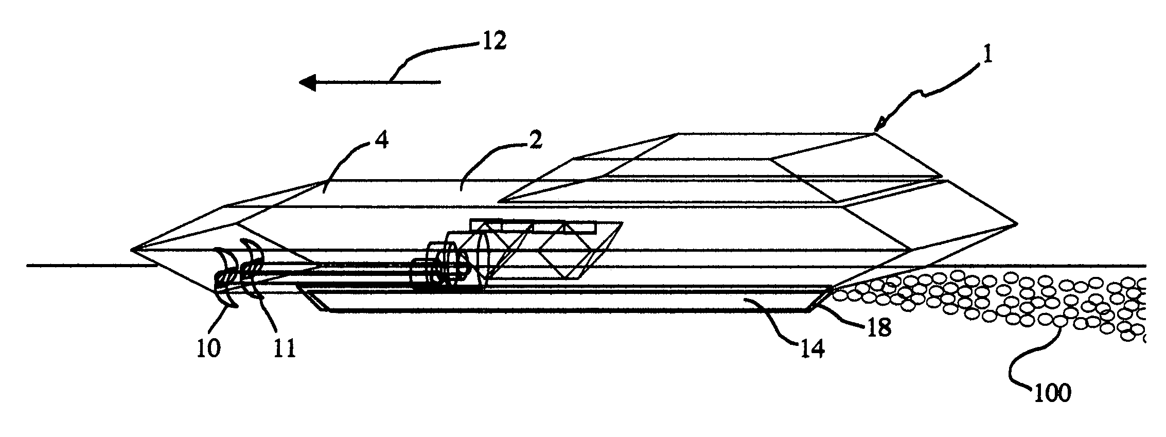
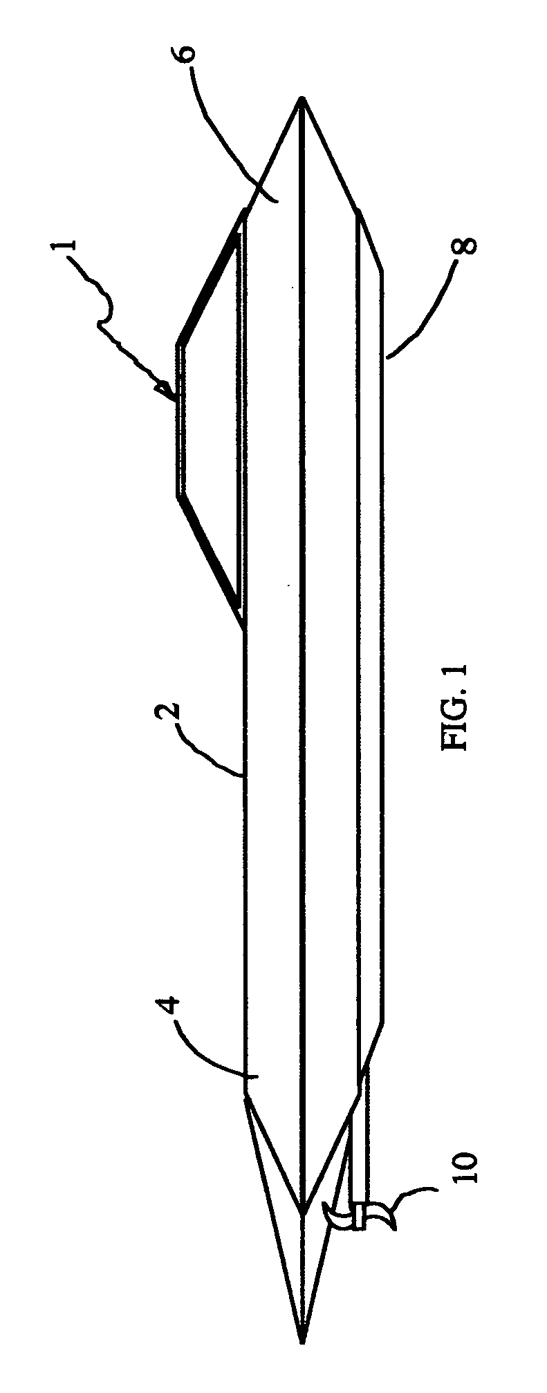
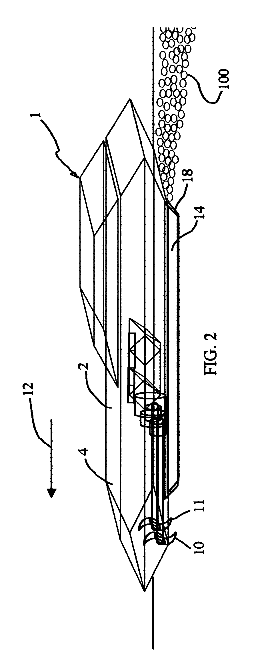
[0036]Waterborne vessel 1, shown in FIGS. 1–4 comprises hull 2 with bow section 4, stern section 6, and flat bottom surface 8. Propellers 10 and 11 are mounted on bow section 4. Propellers 10 and 11 are water surface-piercing propellers, that is they are positioned such that the upper halves of the propellers, that is the upper portions of the propeller blades as the propellers are rotating, are substantially above the surface of the water. Linear rail members 14 and 16 run longitudinally along the lateral sides of bottom surface 8, forming channeled space 18, between the rail members.

[0037]When propellers 10 and 11 are actuated, vessel 1 is propelled in forward direction 12. Since the propellers are partially rotating above the water's surface, they draw air into the ambient water. The air intermixes with the water to create air bubbles 100 at the bow of the vessel. As vessel 1 proceeds in forward direction 12, bubbles 100 travel rearwards directly under bottom surface 8 and are co...


PUM


Abstract

A bow mounted vessel propulsion system is designed to exploit the characteristics of a self-producing vessel lubricating boundary layer of air or air bubbles formed during water surface interaction by the vessel's hull during vessel movement. This boundary layer of air / air bubbles will be produced at the bow of the vessel and, during forward motion, is superimposed upon the surface of the water as the vessel's hull passes over, reducing the frictional drag of the hull as it moves across and through the water. The system has a propulsion means such as a water surface-piercing propeller or water jet nozzles, which will propel the vessel forward and, at the same time, by action of propeller rotation (drawing air into and intermixing) in the water or water jet movement, will create the air bubbles which produce the hull-lubricating phenomenon. The hull is a substantially flat-bottomed planning hull with two linear rails on each lengthwise outer edge of the bottom surface of the hull. The rails extend downward into the water at a sufficient depth to be able to keep the boundary layer of air bubbles from escaping out from the sides of the hull bottom when the vessel is in forward motion.

Description

BACKGROUND OF THE INVENTION[0001]Propulsion of waterborne vessels is most often accomplished by positioning one or more propellers or other propulsion means at or near the stern of the vessel. This common arrangement provides the motive force to effectively compel and transport the hull of the vessel forward through the water. However, such vessel movement, especially for high-speed conveyance, produces substantial surface drag along the hull of the vessel. This results in adverse operations, including reduction of speed and loss of fuel efficiency.[0002]While there have been some minimal attempts to employ bow-mounted forward propulsion systems for the forward movement of waterborne vessels, see, for example, U.S. Pat. No. 4,324,551, and planning hulls employing controlled air films, see, for example, U.S. Pat. No. 4,031,841, none of these prior systems have truly resulted in practical, effective, or efficient bow propulsion systems which have addressed the problem of hull surface ...

Claims


Application Information

Patent Timeline
Patent Type & Authority Patents(United States)
IPC IPC(8): B63B1/34
CPCB63B1/38B63H1/18B63H5/07B63H5/125B63H11/113B63B2001/201Y02T70/122B63H2005/005B63H5/08B60F3/0007Y02T70/10
Inventor ADAMS, ROBERT D.
Owner ADAMS ROBERT D
Learn More