Self cleaning boiler and steam generator

a self-cleaning and steam generator technology, applied in fire-box steam boilers, instruments, lighting and heating apparatus, etc., can solve the problems of uncontrollable water supply and waste water discharge, and achieve the effect of optimizing water supply and maximizing heat us

Active Publication Date: 2006-08-29
AMERICAN GRIDDLE CORP
View PDF4 Cites 30 Cited by
  • Summary
  • Abstract
  • Description
  • Claims
  • Application Information

AI Technical Summary

Benefits of technology

[0006]It is an object of the present invention to provide a steam generator boiler that optimizes the supply of water and maximizes the use of heat from the discharged water for preheating the supply water.

Problems solved by technology

However, the supply of water and the discharge of the waste water was not controlled to optimize the supply of water and to maximize the use of the heat from the discharged water for preheating the supply water.

Method used


Image

  • Self cleaning boiler and steam generator
  • Self cleaning boiler and steam generator
  • Self cleaning boiler and steam generator

Examples


Embodiment Construction

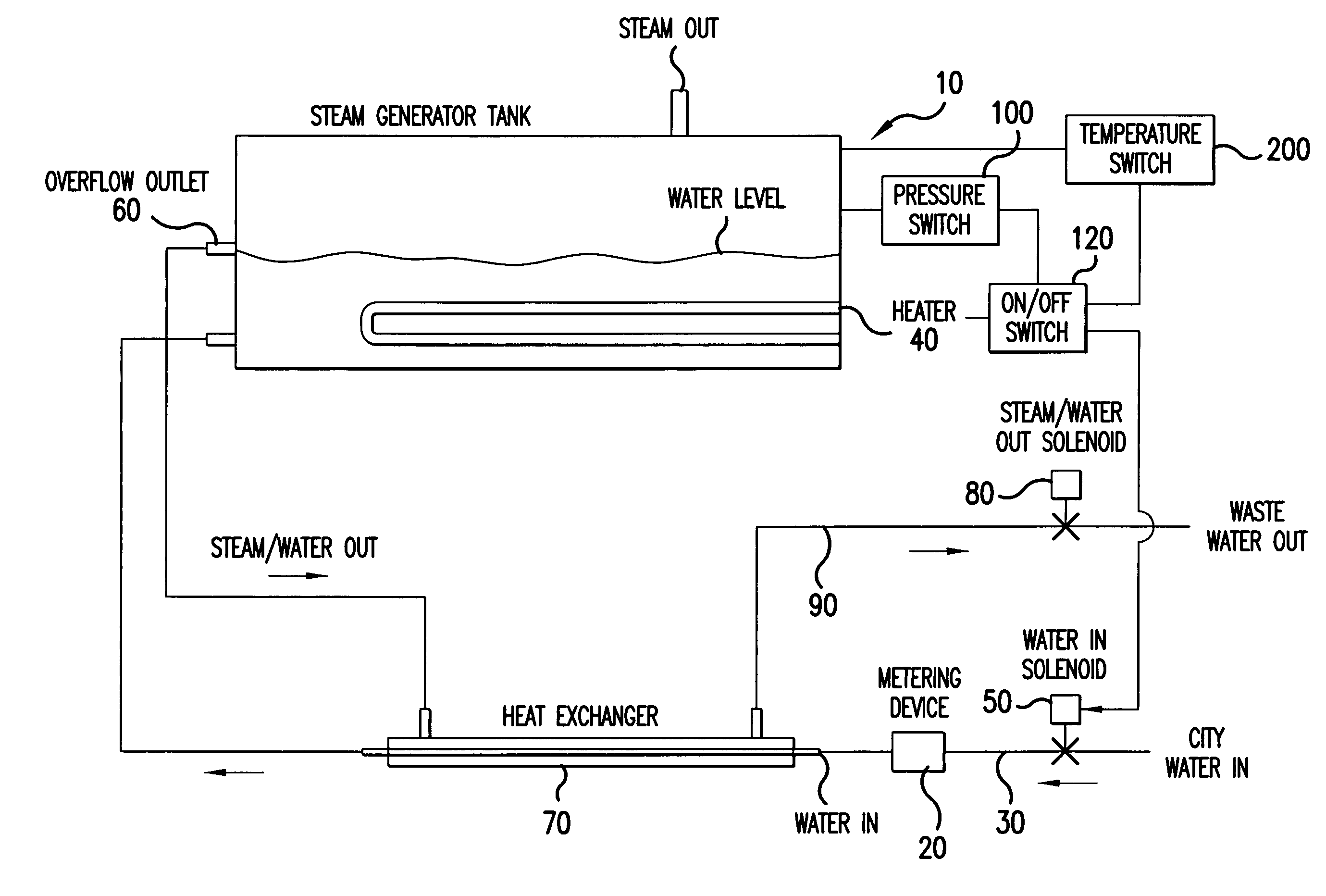
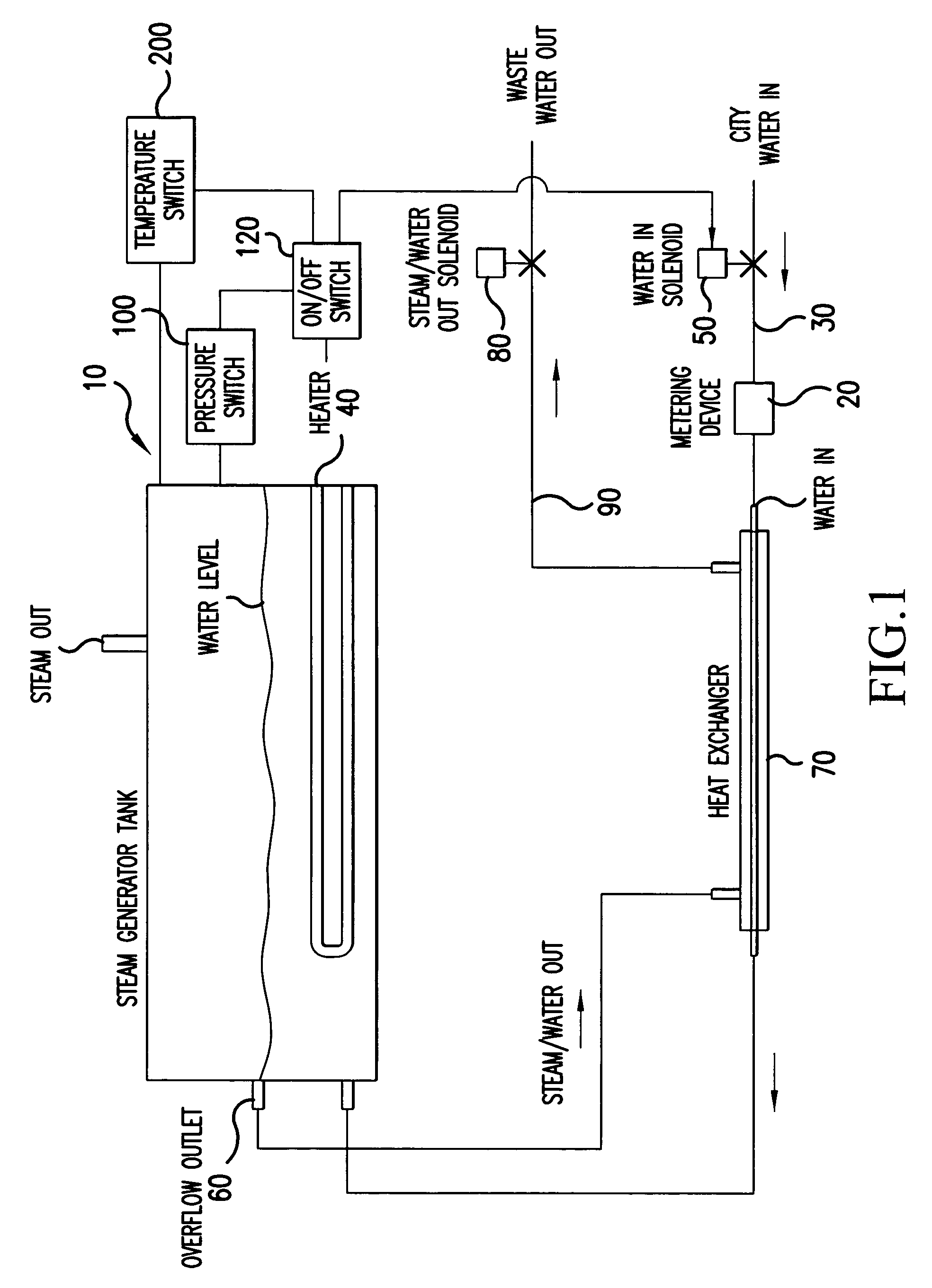
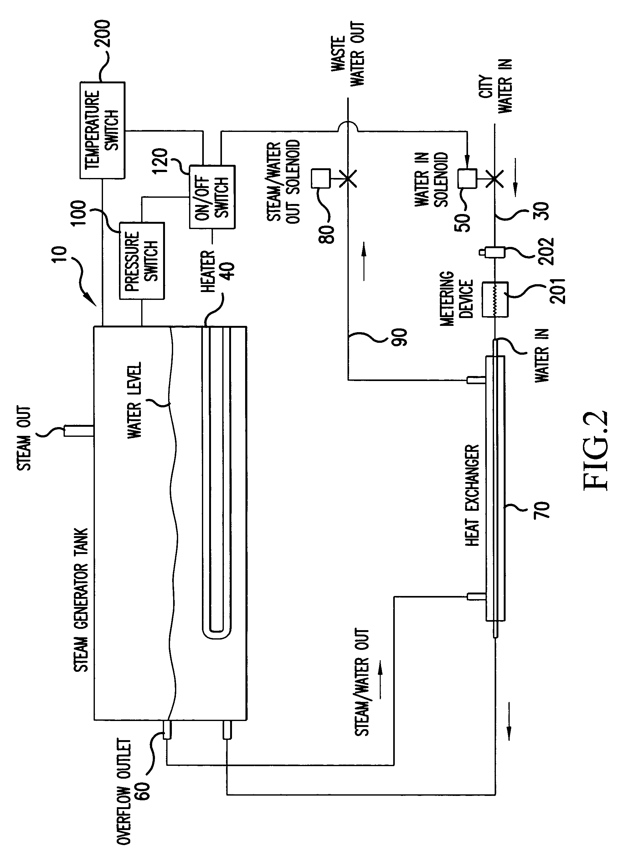
[0012]As illustrated in FIGS. 1 and 2, a steam generator boiler 10 operates by utilizing a metering device 20 in the inlet 30 of the boiler or steam generator 10 to regulate the flow of water to the boiler 10 by calculating the amount of water required based on wattage or BTU's generated by the heaters 40. The boiler or steam generator heaters 40 would be operated by a pressure switch or thermostat, not shown, which would also operate the solenoid valve 50 on the inlet side 30 for the supply of water to the steam generator tank. Thus, water is added every time the heaters 40 are energized.

[0013]A pressure switch 100 would include a pressure sensor located within the boiler or steam generator 10 for determining the pressure inside the boiler or steam generator 10. When the pressure within the boiler or steam generator 10 rises above a predetermined pressure, the pressure within the boiler or steam generator 10 would actuate the on / off switch 120 and turn off the heaters 40 and turn o...


PUM


Abstract

A steam generator boiler for generating steam is connected to a supply conduit for supplying water to the boiler with a supply valve for controlling the supply of water through the supply conduit. A heater supplies heat to the boiler for generating steam with a discharge conduit for discharging excess impure water therefrom. A metering device is operatively connected to the supply conduit for regulating the flow of water to the boiler by calculating the amount of water required based on wattage or BTU's generated by the heater. A pressure switch or thermostat is provided for operating the boiler and the supply valve on the supply conduit for supplying water to the boiler to permit water to be added every time the heater is energized. In addition, a heat exchanger is provided for receiving discharged heated water from the steam generator and preheating water supplied to the steam generator.

Description

CROSS-REFERENCE TO RELATED APPLICATIONS[0001]The present application is related to U.S. Provisional Application No. 60 / 498,647 filed on Aug. 29, 2003 the entire contents of which are hereby incorporated by reference and the priority is claimed under 35 USC 119(e).BACKGROUND OF THE INVENTION[0002]1. Field of the Invention[0003]The purpose of this invention is to have a boilers or steam generator that is self cleaning, requires no floats or level controls and reclaims heat that would normal be dissipated into the air or down the drain.[0004]2. Description of Background Art[0005]Hithertofore, steam generator boilers were available that operate by supplying a quantity of water to a steam generator boiler for producing steam. However, the supply of water and the discharge of the waste water was not controlled to optimize the supply of water and to maximize the use of the heat from the discharged water for preheating the supply water.SUMMARY AND OBJECTS OF THE INVENTION[0006]It is an obje...

Claims


Application Information

Patent Timeline
Patent Type & Authority Patents(United States)
IPC IPC(8): F22B37/46F22B1/28
CPCF22B1/284
Inventor TIPPMANN, VINCENT P.
Owner AMERICAN GRIDDLE CORP
Why Eureka
Try Eureka