Motor vehicle front portion assembly provided with improved fastening and position-adjustment means, and a motor vehicle including such an assembly

a technology for motor vehicles and front parts, which is applied in the direction of vehicle bodies, superstructure subunits, and monocoque constructions, etc., can solve the problems of relatively considerable deformation of the fender front portion over the life of the vehicle, and the uncontrollable adjustment of the orientation and position of the headlight unit supported by the beam

Active Publication Date: 2006-08-29
FAURECIA BLOC AVANT
View PDF11 Cites 23 Cited by
  • Summary
  • Abstract
  • Description
  • Claims
  • Application Information

AI Technical Summary

Benefits of technology

[0011]An object of the invention is to remedy that drawback, and to propose a vehicle front portion assembly of the above type that is compatible with using a fender front portion which is not made of metal, and in particular which is made of a plastics material, and that, for this purpose, preserves the adjustments of the headlight units from the effects of deformation of the fender.
[0016]so that a connection with the possibility of sliding along said third axis is provided between the second end of the beam and the fender front portion, after assembly, via said centering and guide part, in order to make relative adjustment movements possible and in order to accommodate deformation of said fender front portion.

Problems solved by technology

Such a choice of technology, which offers certain advantages, nevertheless results in the fender front portions undergoing relatively considerable deformation over the life of the vehicle.
Via the connection existing between the fender front portion and the corresponding beam, such deformation can, after the front portion assembly of the vehicle has been assembled, and during the life of the vehicle, give rise to significant deformation of the beam, and thereby cause uncontrollable misadjustment of the orientation and of the position of the headlight unit supported by the beam.

Method used


Image

  • Motor vehicle front portion assembly provided with improved fastening and position-adjustment means, and a motor vehicle including such an assembly
  • Motor vehicle front portion assembly provided with improved fastening and position-adjustment means, and a motor vehicle including such an assembly
  • Motor vehicle front portion assembly provided with improved fastening and position-adjustment means, and a motor vehicle including such an assembly

Examples


Embodiment Construction

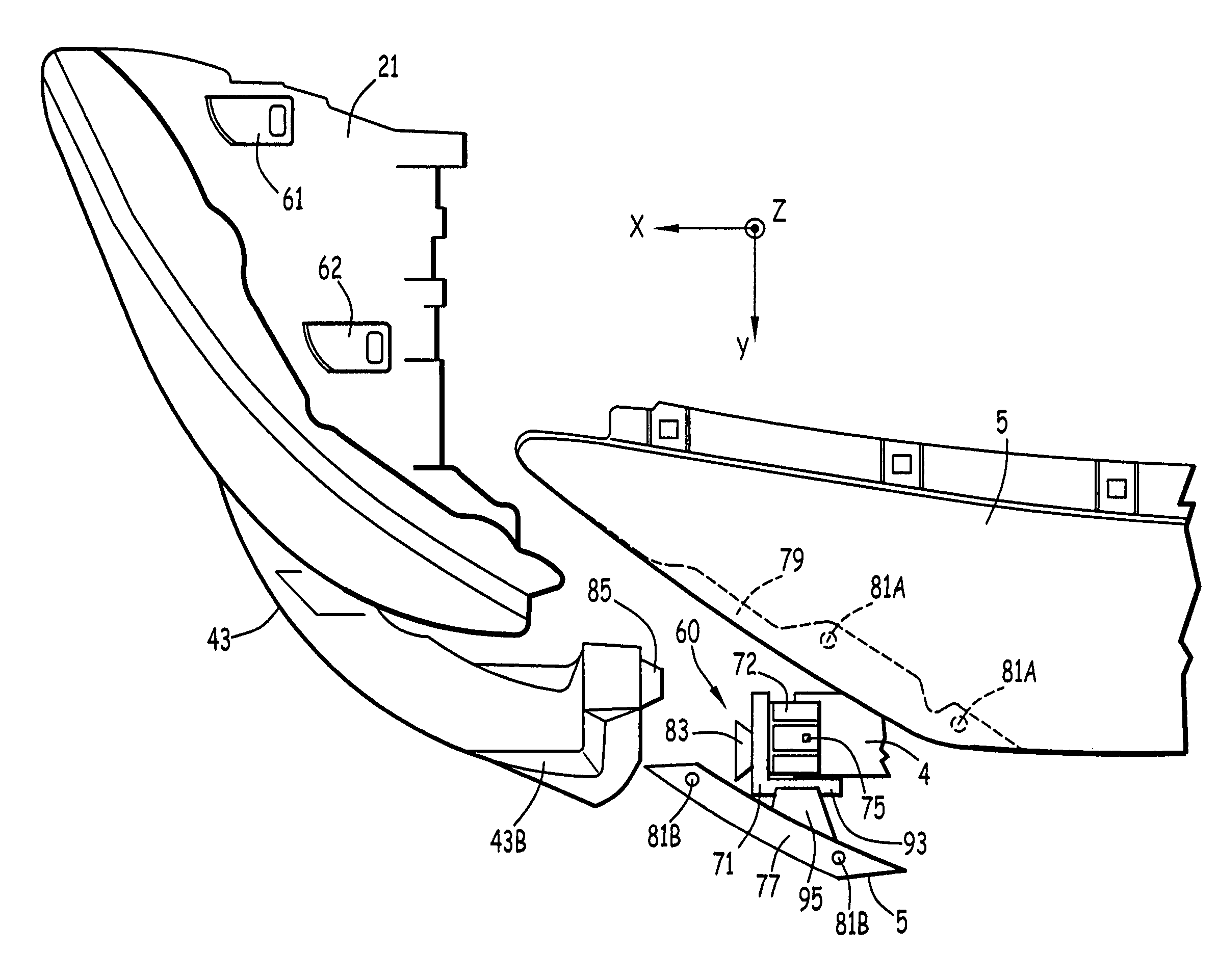
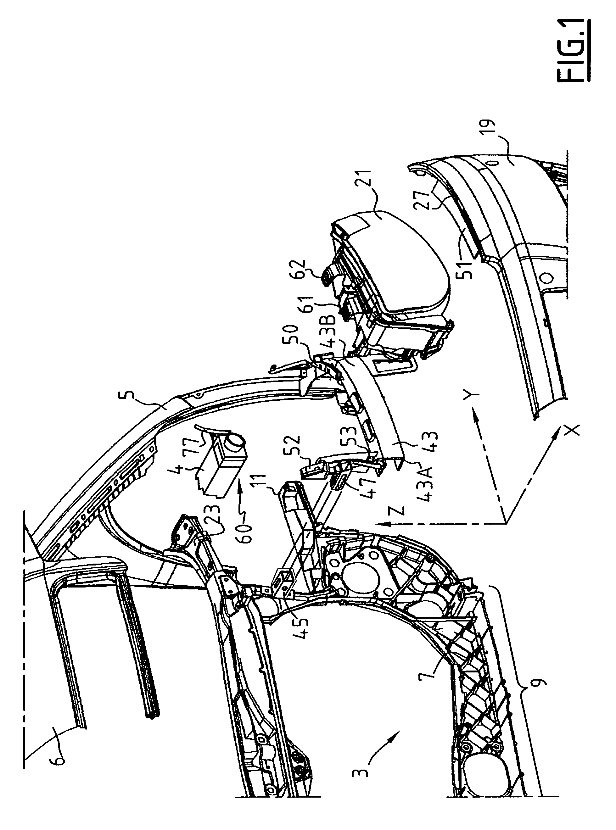
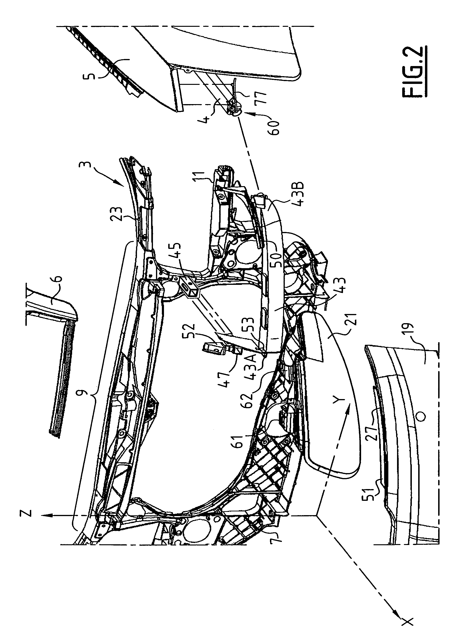
[0037]FIGS. 1 and 2 show a motor vehicle front portion assembly comprising a front unit 3 (shown in part), a structural front portion 4, and a front end 5 of a fender. A front end 6 of the hood of the vehicle is also shown.

[0038]FIGS. 1 and 2, and the other figures, are oriented relative to three axes X, Y, Z that correspond to the usual orientation of the vehicle, namely respectively the longitudinal axis X oriented in the forward direction, the transverse axis Y oriented from right to left, from the driver's point of view, and the vertical axis Z oriented from bottom to top. All of the terms used in the description below and that indicate a direction or a position should be understood with reference to this system of axes.

[0039]The vehicle front portion shown in FIGS. 1 and 2 is symmetrical or almost symmetrical about a vertical midplane of the vehicle. For reasons of clarity, only the portion situated on the left of the vehicle is shown in the figures and described.

[0040]The fron...


PUM


Abstract

The assembly includes:a front face;a structural front portion (4);a fender front portion (5);a flexible beam (43); anda headlight unit fastened to said beam (43).It further comprises:a centering and guide part (71) fastened to the structural front portion, in a position that can be adjusted, during assembly, along three axes (X, Y, Z);fastening and centering means (83, 85) for fastening the end (43B) of the beam to said part (71) and for centering it thereon; andguide means (93, 95) for guiding the fender front portion (5) on said part (71), providing a sliding connection slidable along one of the three axes (X), making relative adjustment movements possible in order to absorb deformation in said fender front portion. The invention is also relates to a motor vehicle including such an assembly.

Description

[0001]The present invention relates to a motor vehicle front portion assembly comprising:[0002]a rigid front face and, on either side of said front face:[0003]a structural front portion;[0004]a fender front portion;[0005]a flexible beam that projects transversely to said front face, said beam having a first end fastened to said front face, and a second end connected to said fender front portion; and[0006]a headlight unit fastened to said beam.BACKGROUND OF THE INVENTION[0007]Such an assembly is described, for example, in Document EP-A-1 232 932.[0008]The structure described in that document makes it possible for the visible outlines of the headlight units to be positioned automatically and permanently relative to the corresponding fender ends and relative to the bumper skin. At the same time, that structure guarantees that the bumper skin is positioned accurately relative to the fender ends.[0009]On certain vehicles, it is chosen for the fender front portions to be made of a plastic...

Claims


Application Information

Patent Timeline
Patent Type & Authority Patents(United States)
IPC IPC(8): B60K7/00B60Q1/04B62D25/08
CPCB62D25/084B60Q1/0408
Inventor LAZZERONI, ERIC
Owner FAURECIA BLOC AVANT
Why Eureka
Try Eureka