Antenna and dielectric substrate for antenna

a dielectric substrate and antenna technology, applied in the direction of resonant antennas, antenna earthings, elongated active element feeds, etc., can solve the problems of difficult control of antenna characteristics, bad vswr characteristics, difficult to control antenna characteristics, etc., to achieve the effect of reducing the volume of the antenna, enhancing the miniaturization, and controlling the antenna characteristi

Inactive Publication Date: 2006-08-29
TAIYO YUDEN KK
View PDF76 Cites 34 Cited by
  • Summary
  • Abstract
  • Description
  • Claims
  • Application Information

AI Technical Summary

Benefits of technology

[0012]Furthermore, another object of the present invention is to provide an antenna having a novel shape that can be miniaturized and make it easy to control the antenna characteristic, and a dielectric substrate for the antenna concerned.
[0024]An antenna dielectric substrate according to a second aspect of the present invention has a layer formed of a dielectric material, and a layer containing a conductor having a cut-out portion formed from an edge portion nearest to a first side surface of the antenna dielectric substrate toward a second side surface opposite to the first side surface. By using such the dielectric substrate, a compact-size antenna having a wide bandwidth (particularly, having an excellent characteristic in a low frequency range) can be implemented.

Problems solved by technology

The antenna resonates at a frequency lower than fL because of the element 1014a, however, the VSWR characteristic is bad.
As described above, though various antennas have been hitherto known, the conventional vertical mount type monopole antennas have problems that their sizes are large, and it is difficult to control the antenna characteristic since it is difficult to control the distance between the radiation conductor and the ground surface.
Furthermore, the conventional symmetrical type dipole antennas also have a problem that it is difficult to control the antenna characteristic since the radiation conductors have the same shape, thereby it is difficult to control the distance between the radiation conductors.
In addition, though it is described that the glass antenna device for the automobile telephone disclosed in JP-A-8-213820 has an excellent sensitivity and directional characteristic at 800 MHz and 1.5 GHz, the bandwidth is not sufficiently broad.
Furthermore, this publication never discloses provision of any cut-out portion.
In addition, though the antenna of U.S. Pat. No. 2002-122010A1 aims at miniaturization, the structure that the driven element is provided within the ground element cannot achieve the sufficient miniaturization because the ground element fully surrounds the driven element.

Method used


Image

  • Antenna and dielectric substrate for antenna
  • Antenna and dielectric substrate for antenna
  • Antenna and dielectric substrate for antenna

Examples


first embodiment

1. First Embodiment

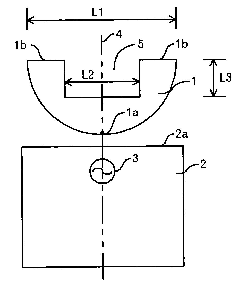
[0053]The structure of an antenna according to a first embodiment of the present invention is shown in FIG. 1A and FIG. 1B. The antenna according to this embodiment is composed of a planar element 1 formed of a semicircular conductive flat plate and having a cut-out portion 5, a ground pattern 2 juxtaposed with the planar element 1, and a high-frequency power source 3 connected to the feed point 1a of the planar element 1. The diameter L1 of the planar element 1 is set to 20 mm, for example. The aperture L2 of the cut-out portion 5 is set to 10 mm, for example, and the rectangular concavity whose depth is L3 (=5 mm) is formed from the top portion 1b (i.e. the edge portion farthest from the feed point 1a) of the planar element 1 toward the ground pattern 2 side, for example. The feed point 1a is located at such a position that the distance between the planar element 1 and the ground pattern 2 is shortest.

[0054]The planar element 1 and the ground pattern 2 are desig...

second embodiment

2. Second Embodiment

[0069]FIG. 6 shows the structure of an antenna according to a second embodiment of the present invention. In this embodiment, an example will be explained in which a planar element 41 which is formed of a semicircular conductive flat plate and is equipped with a cut-out portion 45, and a ground pattern 42 are formed on a printed circuit board (for example, a resin board formed of material such as FR-4, Teflon (registered trademark) or the like) having a dielectric constant of 2 to 5.

[0070]The antenna according to the second embodiment comprises the planar element 41, the ground pattern 42 juxtaposed with the planar element 41, and a high-frequency power source connected to the planar element 41. The high-frequency power source is omitted from the illustration of FIG. 6. The planar element 41 is equipped with a projecting portion 41a which is connected to the high-frequency power source and constitutes a feed point, a curved portion 41b opposite to a side 42a of t...

third embodiment

3. Third Embodiment

[0074]FIG. 8 shows the structure of an antenna according to a third embodiment of the present invention. In this embodiment, an example will be explained in which a planar element 51 which is formed of a rectangular conductive flat plate and equipped with a cut-out portion 55, and a ground pattern 52 are formed on a printed circuit board (FR-4, Teflon (registered trademark) or the like) having a dielectric constant of 2 to 5.

[0075]The antenna according to the third embodiment comprises the planar element 51, the ground pattern 52 juxtaposed with the planar element 51, and a high-frequency power source connected to the planar element 41. The high-frequency power source is omitted from the illustration of FIG. 8. The planar element 51 is equipped with a projecting portion 51a which is connected to the high-frequency power source and constitutes a feed point, a bottom side 51a opposite to a side 52a of the ground pattern 52, lateral side portions 51b connected vertic...


PUM


Abstract

An antenna comprises a ground pattern, and a planar element that is fed and equipped with a cut-out portion provided from the farthest edge portion formed from the feed position toward the ground pattern side, and the ground pattern and the planar element are juxtaposed with each other. The cut-out portion enables to further miniaturize the antenna and secure current paths to obtain radiation in a low-frequency range. Since the ground pattern and the planar element are juxtaposed with each other, the mount volume of the antenna can be reduced, and the antenna characteristic, particularly the impedance characteristic, can be easily controlled, and the bandwidth can be widened.

Description

TECHNICAL FIELD OF THE INVENTION[0001]The present invention relates to a wide bandwidth antenna.BACKGROUND OF THE INVENTION[0002]For example, JP-A-57-142003 discloses the following antennas. That is, it discloses a monopole antenna in which a flat-plate type radiation element 1001 having a disc shape is erected vertically to an earth plate or the ground 1002 as shown in FIGS. 22A-1 and 22A-2. This monopole antenna is designed so that a high-frequency power source 1004 and the radiation element 1001 are connected to each other through a power feeder 1003 and the height of the top portion of the radiation element 1001 is set to a quarter wavelength. Furthermore, it also discloses a monopole antenna in which a flat-plate type radiation element 1005 whose upper peripheral edge portion has a shape extending along a predetermined parabola is erected vertically to an earth plate or the ground 1002. Still furthermore, it discloses a dipole antenna in which two radiation elements 1001 of the...

Claims


Application Information

Patent Timeline
Patent Type & Authority Patents(United States)
IPC IPC(8): H01Q1/38H01Q1/24H01Q1/36H01Q1/48H01Q5/00H01Q9/28H01Q9/38H01Q9/40
CPCH01Q9/40H01Q1/38
Inventor OKADO, HIRONORI
Owner TAIYO YUDEN KK
Why Eureka
Try Eureka