Microstrip antenna

a dipole antenna and microstrip technology, applied in individual energised antenna arrays, resonant antennas, waveguide types, etc., can solve the problems of limited usefulness of dipole antennas in devices, printed circuit boards, etc., and achieve the effect of improving gain

Inactive Publication Date: 2006-08-29
LAIRDTECH INC
View PDF4 Cites 42 Cited by
  • Summary
  • Abstract
  • Description
  • Claims
  • Application Information

AI Technical Summary

Benefits of technology

[0005]In one embodiment, an antenna is provided that comprises (a) a power feed network; (b) a ground plane located in proximity to the power feed network and separated therefrom by a dielectric material and electrically coupled thereto when an RF signal is provided to the power feed network; and (c) a plurality of radiating elements operably interconnected with the power feed network and operable to transmit and receive RF signals having frequencies in a predetermined frequency range. The frequency range has a center frequency and each of the radiating elements is interconnected with the feed network and located approximately one-quarter wavelength from an edge of the ground plane at the center frequency. The ground plane is operable to act as a reflector relative to the radiating elements over the frequency range thereby providing enhanced gain for the antenna over the frequency range.

Problems solved by technology

The narrow bandwidth of operation causes printed circuit board, dipole antennas to have limited usefulness in devices required to operate over large bandwidths, such as the IEEE 802.11a frequency band, which is 5.15 to 5.85 GHz.

Method used


Image

  • Microstrip antenna
  • Microstrip antenna
  • Microstrip antenna

Examples


Embodiment Construction

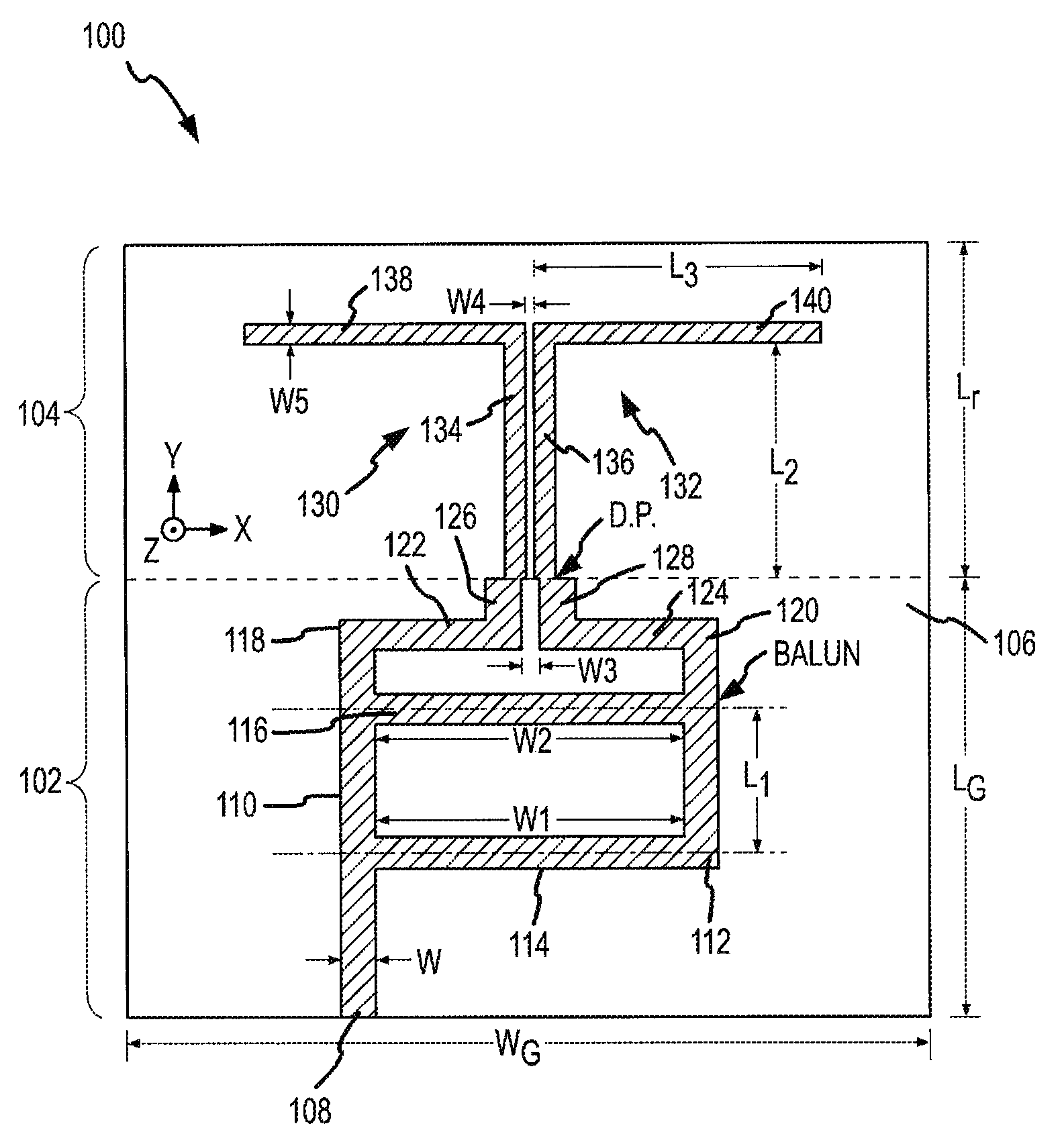
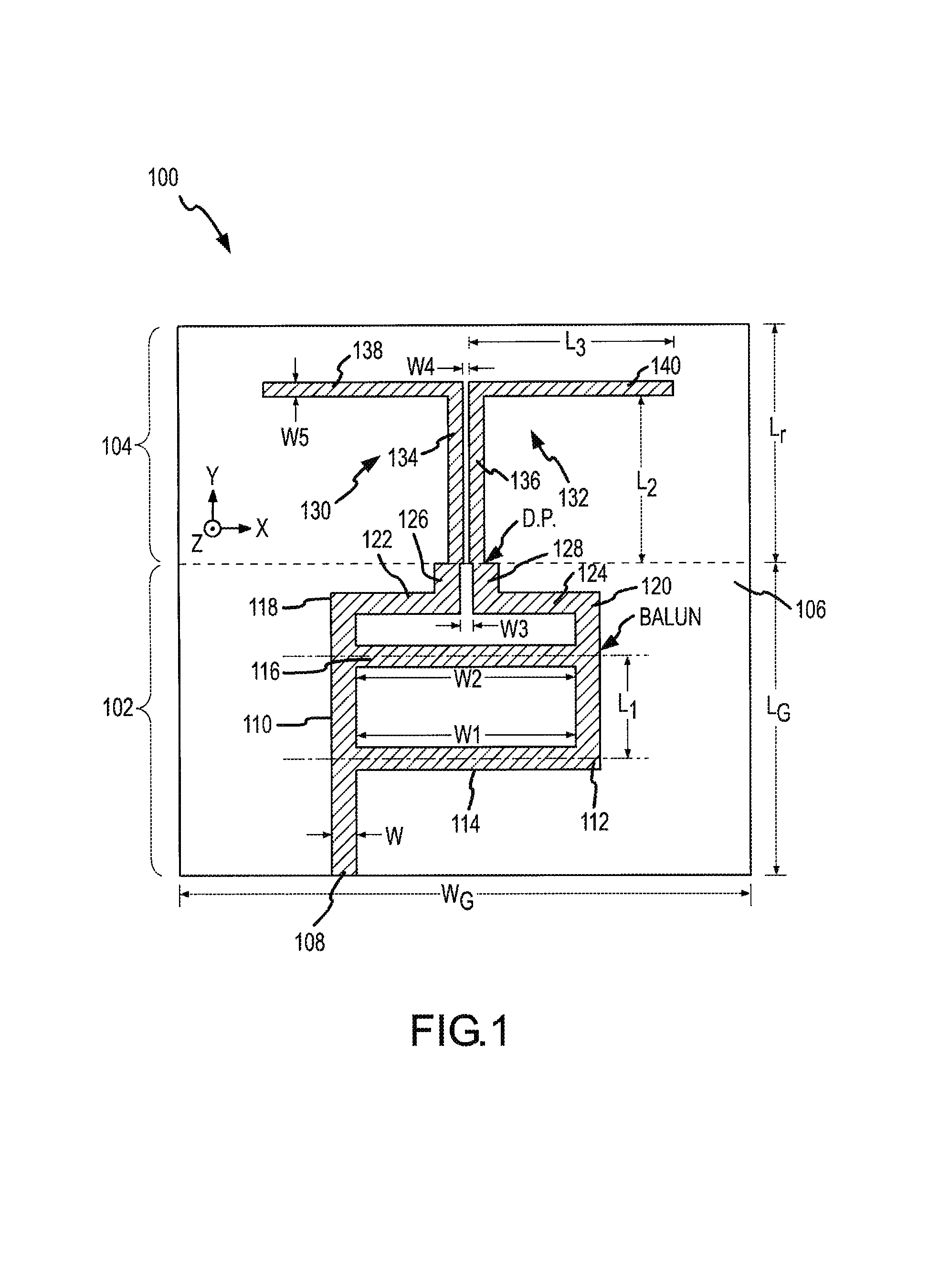
[0016]The present invention will be described with reference to the present invention. Referring first to FIG. 1, a microstrip antenna 100 is shown. Microstrip 100 includes a power feed network 102 and a plurality of radiating elements 104. Power feed network 102 is coupled to a ground plane 106. Power feed network 102 is shown as a ladder balun. The ladder balun feed has a feed point 108, a first leg 110, and a second leg 112. While the legs are shown as substantially parallel, legs 110 and 112 can converge or diverge from feed point 108 for different effects. Feed point 108 is connected to a feed end of first leg 110. As shown, a first connecting element 114 of a length W1 connects first leg and second leg at a feed end of second leg 112. A second connecting element 116 connects first leg and second leg as well. Because legs 110 and 112 are substantially parallel, second connecting element 116 has a length W2. Length W2 is equal to W1 for the case where legs 110 and 112 are substa...


PUM


Abstract

An antenna is provided having a relatively wide bandwidth of operation. The antenna may be a printed circuit board dipole antenna having a ladder balun feed network coupled to a ground plane and dipole radiating elements located about one-quarter wavelength from an edge of the ground plane. The ground plane acts as a reflector to increase antenna gain. A plurality of the antennas may be provided in an array configuration with antennas being located in relatively close proximity and being isolated from other antennas in the array. An array of antennas may be used to provide a wireless link in a wireless network utilizing a IEEE 802.1X frequency band.

Description

CROSS-REFERENCE TO RELATED APPLICATIONS[0001]This application claims the benefit of U.S. Provisional Patent Application No. 60 / 565,032, filed on Apr. 23, 2004, entitled “MICROSTRIP ANTENNA”, the entire disclosure of which is hereby incorporated by reference.FIELD OF THE INVENTION[0002]The present invention relates to a microstrip antenna and, more particularly, to a microstrip dipole antenna having a ladder balun feed.BACKGROUND OF THE INVENTION[0003]Printed circuit board, dipole antennas are good functional antennas, but tend to operate in relatively narrow bandwidths. The narrow bandwidth of operation causes printed circuit board, dipole antennas to have limited usefulness in devices required to operate over large bandwidths, such as the IEEE 802.11a frequency band, which is 5.15 to 5.85 GHz. Thus, it would be desirous to construct a printed circuit board, dipole antenna having a wide bandwidth of operation.SUMMARY OF THE INVENTION[0004]The present invention provides an antenna ha...

Claims


Application Information

Patent Timeline
Patent Type & Authority Patents(United States)
IPC IPC(8): H01Q1/50H01Q1/38H01Q9/28H01P5/10H01Q9/04H01Q21/20
CPCH01P5/10H01Q21/205H01Q9/285H01Q13/08H01Q1/24
Inventor BANCROFT, RANDY
Owner LAIRDTECH INC
Why Eureka
Try Eureka