Dual mode collimated communications transceiver

a collimated communication and transceiver technology, applied in the field of light or infrared transceivers, can solve the problems of limiting the distance over which data transmission can occur, increasing the amount of light energy emitted by the led, and limiting the range of communications, so as to achieve a narrow field of view and a longer distance operation

Inactive Publication Date: 2006-08-29
IBM CORP
View PDF13 Cites 3 Cited by
  • Summary
  • Abstract
  • Description
  • Claims
  • Application Information

AI Technical Summary

Benefits of technology

[0011]When the system is in the collimated position, the light or infrared emitting device such as an LED will have it's normally wide angle cone of light focused by the mirror into a collimated beam of light which is preferably oriented horizontally to permit long distance communications in the normal place of operation of a commercial enterprise such as an office. Conversely, any light communications which are within the field of view of the mirror will be focused on the receiving element (sensor) in the optically active portion of the communications module likewise permitting longer distance operation than when used in the non-collimated position, as it will have a narrower field of view.

Problems solved by technology

However, as will be well recognized, the range of communications is limited by the amount of power which can be emitted by the emitter.
This limits the distance over which data transmission can occur as the power density will fall off beyond the density required for effective transmission when communicating nodes are separated by excessive distance.
If increased range is desired, the amount of light energy emitted by the LED could possibly be increased; however, this will be limited by the nature of the LED employed and by maximum safe limitations imposed by government or safety regulations to protect users from excessive exposure to infrared light
This would typically preclude more than two devices from communicating using a collimated beam unless all devices or nodes in the LAN were lined up with the beam or a mirror system was used to reflect the beams used to the different nodes, all of which is unnecessarily complex for simple operation.

Method used


Image

  • Dual mode collimated communications transceiver
  • Dual mode collimated communications transceiver
  • Dual mode collimated communications transceiver

Examples


Embodiment Construction

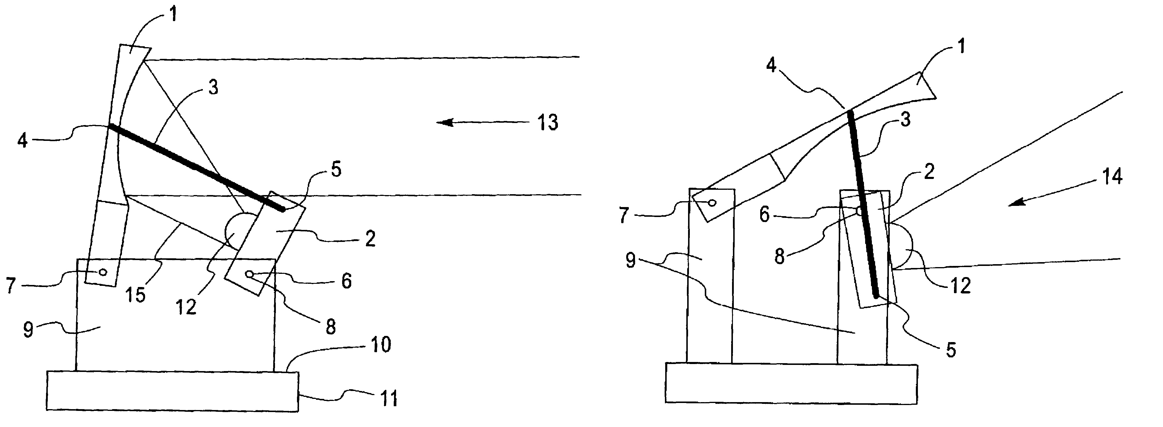
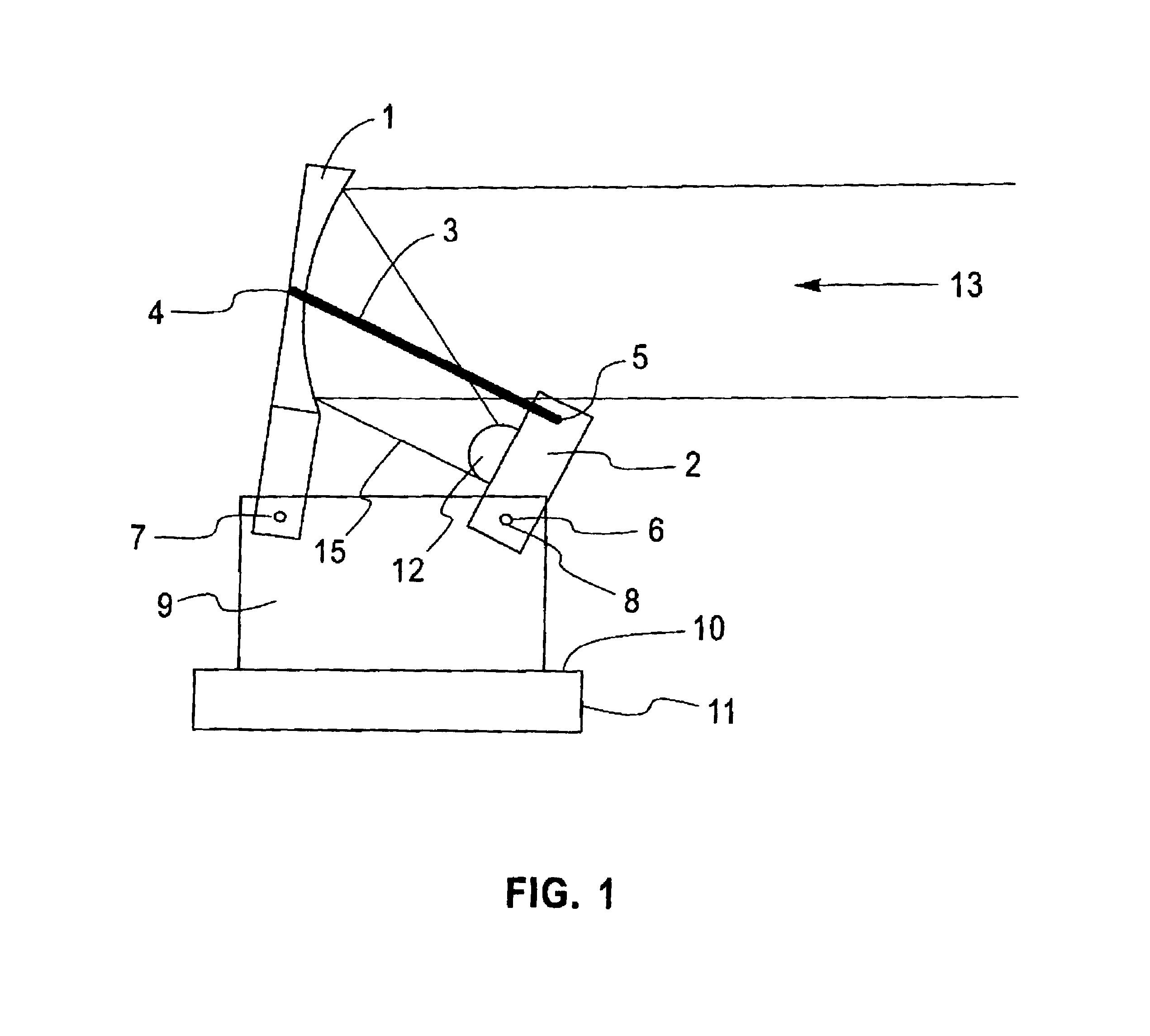
[0015]FIG. 1 illustrates an embodiment of the invention in the collimated or narrow angle mode of operation. The collimator, an off-access parabolic minor 1 which is in a substantially upright position indicated in this figure focuses light emitted from the optically active area 12 of communications module 2 which is positioned at the mirror focal point 15 into a collimated beam (or narrow) of light 13 for transmission substantially horizontally to another optically active system, such as a receiver or a data processing computer system. The most prevalent system in use for light communication is infrared light. For this purpose the optically active area 12 of the communications module 2 would preferably include an infrared LED (which is commonly available and needs no further description). The LED chosen would preferably conform to accepted commercial and safety standards and comply with the IrDA association requirements to assure compatibility with communications with other data pr...


PUM


Abstract

The invention provides an optical communications system having a dual mode of operation. It includes a communications module having an optically active portion with a wide-angle view; a light collimator; and a connector connecting the communications module and the light collimator to permit the module and collimator to be selectively positioned in a collimated or non-collimated position. When it is the collimated position, the communications module is positioned at the focal point of the collimator, and when in a non-collimated position the communications module is positioned away from focal point of the collimator; so that the communications system has a narrow field of view when operated in the collimated position, and has a wide field of view when operated in the non-collimated position.

Description

FIELD OF THE INVENTION[0001]This invention relates to light or infrared transceivers which are capable in operating in different configurations including collimated and wide angle modes of operation.BACKGROUND OF THE INVENTION[0002]In order to secure increase flexibility, data processing systems have migrated to LAN (Local Area Network) communication systems so that individual computer workstations can be connected to data servers, printers, and other facilities. Up until recently, most of these LAN systems have been wired so that when a user wished to connect to the LAN the user must secure a physical or wired connection to the LAN in order to participate in communications on the LAN.[0003]In order to secure a more flexible system to dispense with wiring and permit a flexible arrangement in which workstations or other devices (which we will collectively call nodes), could be added to or removed from wireless LANs were developed. The most convenient way that has been found to operat...

Claims


Application Information

Patent Timeline
Patent Type & Authority Patents(United States)
IPC IPC(8): H04B10/30H04B10/10H04B10/00H04B10/11H04W88/00
CPCH04B10/112H04B10/114H04B10/40
Inventor HELMS, RICHARD MORGANTAGLIONE, JOHN V.
Owner IBM CORP
Why Eureka
Try Eureka