Noise shaping technique for spread spectrum communications
Inactive Publication Date: 2006-08-29
INTERDIGITAL TECH CORP
View PDF51 Cites 2 Cited by
Summary
Abstract
Description
Claims
Application Information
AI Technical Summary
This helps you quickly interpret patents by identifying the three key elements:
Problems solved by technology
Method used
Benefits of technology
[0005]The present invention is an improvement of a conventional spread spectrum communication system, having a transmitter and a receiver. It is an aspect of the present invention to increase the signal to noise ratio of a spread spectrum system by up-converting, or equivalently, frequency translating the signal, or up-shifting the spectrum of the signal to be sent, before spreading. Spreading, as used here, means spread spectrum encoding. In the present invention, the up-converted signal is transmitted and then received and then down-converted, after despreading. This has the advantageous effect of reducing the effect of self-interference and noise when the signal is received, when using a receiver according to the principles of the present invention.
[0006]In the present invention, the spectrum of the signal to be transmitted is shifted or frequency translated to
Problems solved by technology
The noise in a spread spectrum system is often largely self-interference, as well as additive Gaussian white noise, which appear in the receiver as an interfering random signa
Method used
Image
Click on the blue label to locate the original text in one second.
Reading with bidirectional positioning of images and text.
Examples
Example
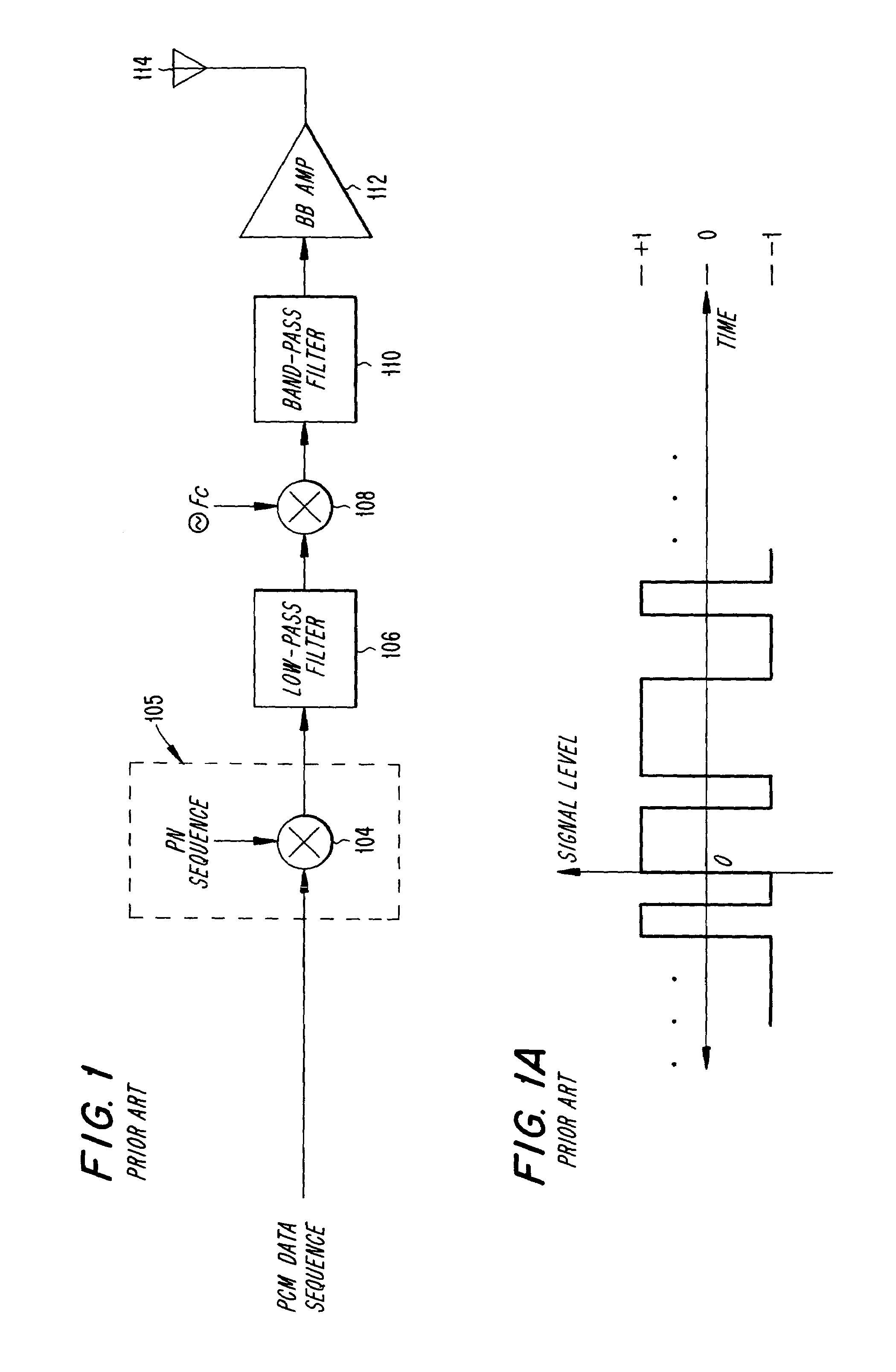
[0033]FIG. 1 shows a typical prior art spread spectrum transmitter. At the left-hand side of FIG. 1, a baseband, pulse coded modulated signal, typically a 32 kilobit per second Adaptive Pulse Code Modulated (ADPCM) speech signal, is applied to the left-hand terminal of mixer 104, which is shown contained within spread spectrum encoder 105. More information about the use and characteristics of spread spectrum encoders may be found in Taub, op. cit., pages 721–727. A pseudonoise (PN) sequence (FIG. 1A) is applied to the upper terminal of mixer 104. Mixer 104 thereby performs a frequency spectrum spreading function by multiplying the PCM data sequence by the PN sequence in the time domain, which is equivalent to convolving the bimodal spectrum of the data sequence with the approximately rectangular spectrum of the PN sequence in the frequency domain. The output of mixer 104 is applied to low-pass filter 106, whose cutoff frequency is equal to the system chip rate, Fcr. The output of fi...
PUM
Abstract
A spread spectrum noise shaper uses a modulation technique to achieve a greater signal-to-noise or signal-to-interference ratio (SNR or SIR). The technique doubles the system SIR, in principle. This doubling yields a doubling in system capacity. SNR is increased by receiving the spread spectrum signal in the presence of less noise near the edge of the spread spectrum bandwidth. The technique requires only small additions to a conventional spread spectrum system, in the form of an extra modulator at the transmitter, and an extra demodulator and filter at the receiver.
Description
CROSS REFERENCE TO RELATED APPLICATION[0001]This application claims priority from U.S. patent application Ser. No. 10 / 029,707, which was filed on Dec. 21, 2001, now U.S. Pat. No. 6,654,407, which is a continuation of U.S. patent application Ser. No. 09 / 679,773, which was filed on Oct. 5, 2000, now U.S. Pat. No. 6,347,111, which is a continuation of U.S. patent application Ser. No. 09 / 192,703, which was filed Nov. 16, 1998, now U.S. Pat. No. 6,148,021, which is a continuation of U.S. patent application Ser. No. 08 / 910,069, which was filed Aug. 12, 1997, now U.S. Pat. No. 5,838,719, which is continuation of U.S. patent application Ser. No. 08 / 542,306, which was filed on Oct. 12, 1995 (now abandoned), which is a continuation of U.S. patent application Ser. No. 08 / 146,650, which was filed on Nov. 2, 1993, now U.S. Pat. No. 5,459,758, which is incorporated by reference as if fully set forth herein.FIELD OF THE INVENTION[0002]The present invention relates to the field of spread spectrum o...
Claims
Application Information
Patent Timeline
Application Date:The date an application was filed.
Publication Date:The date a patent or application was officially published.
First Publication Date:The earliest publication date of a patent with the same application number.
Issue Date:Publication date of the patent grant document.
PCT Entry Date:The Entry date of PCT National Phase.
Estimated Expiry Date:The statutory expiry date of a patent right according to the Patent Law, and it is the longest term of protection that the patent right can achieve without the termination of the patent right due to other reasons(Term extension factor has been taken into account ).
Invalid Date:Actual expiry date is based on effective date or publication date of legal transaction data of invalid patent.