

Adaptive optics apparatus and imaging apparatus including the same
- Summary
- Abstract
- Description
- Claims
- Application Information
AI Technical Summary
Benefits of technology
Problems solved by technology
Method used
Image

Examples
first embodiment
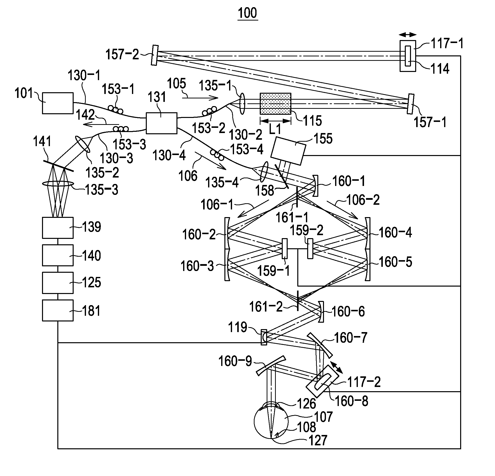
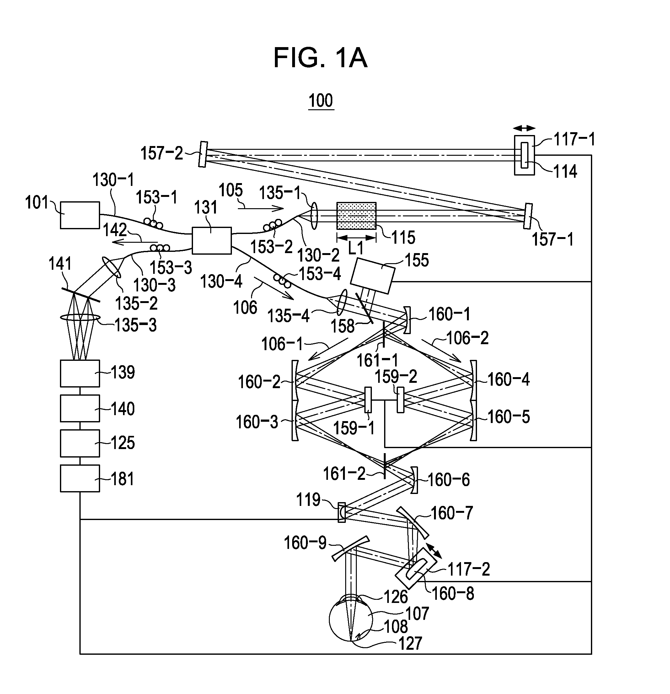
[0019]An OCT apparatus according to a first embodiment of the present invention will be described. In particular, in the first embodiment, an OCT apparatus including an adaptive optics system that acquires a tomographic image (OCT image) of a subject's eye with high horizontal resolution will be described. The first embodiment is a Fourier domain OCT apparatus that corrects the aberration of the subject's eye by using two reflective spatial light modulators and acquires a tomographic image of a subject's eye. Such an OCT apparatus can acquire a good tomographic image irrespective of the diopter or the aberration the subject's eye. The two reflective spatial light modulators are parallely disposed in the OCT apparatus. Here, the spatial light modulators are reflective liquid crystal spatial phase modulators that employ the orientation of liquid crystal. As long as the spatial light modulators can modulate the phase of light, materials other than liquid crystal may be used.
[0020]Refer...
second embodiment
[0037]An OCT apparatus according to a second embodiment of the present invention will be described. In particular, an OCT apparatus including an adaptive optics system that acquires a high horizontal resolution tomographic image (OCT image) of a subject's eye will be described. The second embodiment is a Fourier domain OCT apparatus that acquires a tomographic image of a subject's eye by correcting the aberration of the subject's eye by using two reflective spatial light modulators. Using the OCT apparatus a good tomographic image can be acquired irrespective of the diopter or the aberration of the subject's eye. Here, the two reflective spatial light modulators are serially disposed. Two wavefront sensors are used to measure the aberration for each polarized beam. First, referring to FIG. 4, the overall structure of the optical system of the OCT apparatus according to the second embodiment will be described. In the second embodiment, the elements the same as those of FIGS. 1A to 1C...
third embodiment
[0044]An OCT apparatus according to a third embodiment, in which one reflective spatial light modulator employing the orientation of liquid crystal is used to correct the aberration, will be described. As described above, in the first and second embodiments, two spatial light modulators respectively modulate the p-polarized light and the s-polarized light so as to correct the aberration. In contrast, as illustrated in FIG. 5, in the third embodiment, one spatial light modulator is used and one of the polarized beams is rotated so that the polarization is aligned, whereby modulation can be performed irrespective of the polarization state of the measuring beam or the return beam. Thus, the third embodiment is characterized by the optical path of the measuring beam. Because the structures of the light source, the reference optical path, the measurement system are the same as those of the first embodiment, the description of these are omitted, and the structure of the optical path of th...
PUM
 Abstract
Description
Claims
Application Information