Method of adaptive signal degradation compensation

a signal degradation and compensation technology, applied in electromagnetic transmission, electrical equipment, transmission, etc., can solve the problems of increasing the bit error rate (ber), inter symbol interference (isi), and the pulse is not recognized above the ambient noise level in the optical channel, so as to maximize the transmission distance, minimize the ber value, and optimize the shape of the receive end pulse

Inactive Publication Date: 2006-08-29
ALTERA CORP
View PDF10 Cites 30 Cited by
  • Summary
  • Abstract
  • Description
  • Claims
  • Application Information

AI Technical Summary

Benefits of technology

[0029]The present invention advantageously optimizes the receive end pulse shape, minimizes the BER value, and maximizes the transmission distance (L) by using a remote end feedback signal to adaptively lock-in a variable phase prechirp transmitter in order to compensate for signal degradation along the fiber. This invention can be used in conjunction with DCF, or any other dispersion compensating elements (DCE), to act as a “mop-up” dispersion

Problems solved by technology

As the signal propagates over the physical fiber, degradations of the signal tend to accumulate with distance and can make a pulse unrecognizable above the ambient noise level in the optical channel.
Such degradations in signal quality can cause bits to be misinterpreted at the receiving end, thereby increasing the bit error rate (BER).
By broadening the pulses, this phenomenon causes inter symbol interference (ISI) where widened pulses encroach on time slots of neighbouring pulses.
The phenomenon of group velocity dispersion (GVD), e.g. chromatic dispersion (CD) and polarization mode dispersion (PMD), as well as fiber non-linearities, e.g. the self-phase modulation (SPM), are significant obstacles to achieving quality communication standards over longer repeaterless transmission distances.
However, even for DSF, the accumulated dispersion across the wavelength band at 1,000 km reach is far beyond a 10 Gbps receiver dispersion tolerance.
The interplay between CD and non-linearities such as SPM, ca

Method used


Image

  • Method of adaptive signal degradation compensation
  • Method of adaptive signal degradation compensation
  • Method of adaptive signal degradation compensation

Examples


Embodiment Construction

[0042]The following description is of a preferred embodiment by way of example only and without limitation to combination of features necessary for carrying the invention into effect.

[0043]The method according to the invention is based on prechirping of the signal phase at the transmitter (Tx) site for suppressing degradation of a transmission wave form due to linear and nonlinear effects in the fiber. Prechirping is a technique that can be performed by altering the phase of the optical signal, and implies imposing a controlled compensatory degradation, or induced phase prechirp. A parameter (C) as defined in EQ 2 is characteristic for the chirp associated with external modulators.

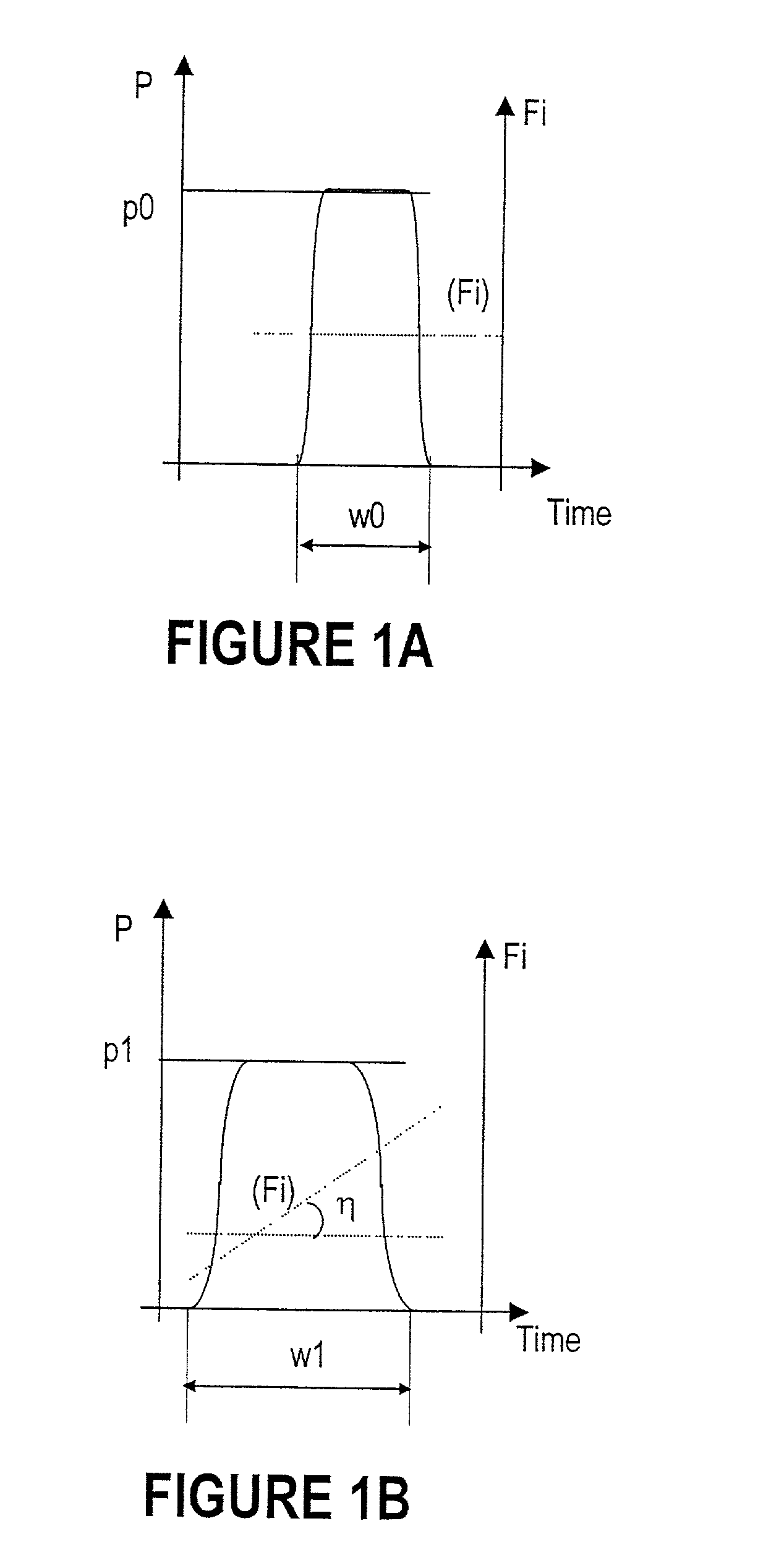
[0044]FIGS. 1A and 1B described next are intended to provide a better view of the field of the invention and the current state of the art.

[0045]FIG. 1A illustrates an optical pulse po sent without compensation over the fiber. The pulse has a width “wo” and a substantially constant instantaneous frequency (...


PUM


Abstract

An iterative process is used to set the phase prechirp of a WDM optical transport system to a system's optimal level that maximizes the signal quality. A signal degradation factor takes into account linear and non-linear effects along the optical path and is used as a receive end feedback signal to control the phase prechirp level at the transmitter site. By using the FEC corrected errors rate as the feedback signal, optimization of signal quality is performed even when the system is running error free. By using an adaptive phase prechirp transmitter, signal degradation compensation can be also performed on a per wavelength basis to compensate for the residual dispersion slope and to allow optimization of individual channels independently of the net link dispersion value.
This method provides more flexibility when using optical switching in core networks, as it allows path optimization to new physical link connectivity, without requiring any change to the optical components such that, significant signal degradation tuning range for a WDM optical transport system is provided.

Description

CROSS REFERENCE TO RELATED APPLICATIONS[0001]This application claims the benefit of U.S. patent application Ser. No. 60 / 227,796 filed Aug. 25, 2000.BACKGROUND OF THE INVENTION[0002]The invention relates generally to optical transport systems and more particularly to an optical fiber transmission system with an adaptive phase prechirp transmitter.[0003]Optical networks are presently the physical medium of choice and maximizing their performance is a constant need. The universal access to communications created by the introduction of Internet has driven the demand for more high-bandwidth networks capable of handling large volumes of data at high speed and low latency.A Composite Signal Degradation Factor[0004]For transmitting data over an optical network, the information is encoded into a series of pulses, or bits. As the signal propagates over the physical fiber, degradations of the signal tend to accumulate with distance and can make a pulse unrecognizable above the ambient noise le...

Claims


Application Information

Patent Timeline
IPC IPC(8): H04B10/04H04B10/18
CPCH04B10/25137
Inventor SAUNDERS, ROSS ALEXANDERNAGARAJAN, RAJKUMARANIS, HANANROBINSON, ANDREWCORBEIL, SACHA
Owner ALTERA CORP
Why Eureka
Try Eureka