Motor drive apparatus, hybrid vehicle drive apparatus using the same, and computer readable recording medium recorded with program for causing computer to perform control of motor drive apparatus

a technology of hybrid vehicles and motor drives, which is applied in the direction of engine-driven generators, propulsion, process and machine control, etc., can solve the problems of unfavorable situation and cost increase, and achieve the effect of preventing meltdown and adhesion or degradation of the contact point of the relay, and preventing an overvoltag

Inactive Publication Date: 2006-08-29
TOYOTA JIDOSHA KK
View PDF35 Cites 74 Cited by
  • Summary
  • Abstract
  • Description
  • Claims
  • Application Information

AI Technical Summary

Benefits of technology

[0014]In view of the foregoing, an object of the present invention is to provide a motor drive apparatus that prevents an overvoltage from being applied to an electric load connected to a primary side of a voltage converter conducting voltage conversion, in the event of a fault of a DC power supply.
[0015]Another object of the present invention is to provide a motor drive apparatus that cuts off a relay to prevent meltdown upon a fault of a DC power supply.
[0016]A further object of the present invention is to provide a hybrid vehicle drive apparatus that prevents an overvoltage from being applied to an electric load connected to a primary side of a voltage converter conducting voltage conversion, in the event of a fault of a DC power supply.

Problems solved by technology

However, if the technique disclosed in Japanese Patent Laying-Open No. 7-87614 is applied when there is a fault in DC power supply B of motor drive apparatus 300, an overvoltage will be applied to the DC / DC converter connected between system relays SR1, SR2 and bidirectional converter 310, causing an unfavorable situation.
In this case, increasing the withstand voltage of the DC / DC converter will lead to a cost increase.

Method used


Image

  • Motor drive apparatus, hybrid vehicle drive apparatus using the same, and computer readable recording medium recorded with program for causing computer to perform control of motor drive apparatus
  • Motor drive apparatus, hybrid vehicle drive apparatus using the same, and computer readable recording medium recorded with program for causing computer to perform control of motor drive apparatus
  • Motor drive apparatus, hybrid vehicle drive apparatus using the same, and computer readable recording medium recorded with program for causing computer to perform control of motor drive apparatus

Examples


Embodiment Construction

[0048]Hereinafter, embodiments of the present invention will be described in detail with reference to the drawings. In the drawings, the same or corresponding portions are denoted by the same reference characters, and description thereof will not be repeated.

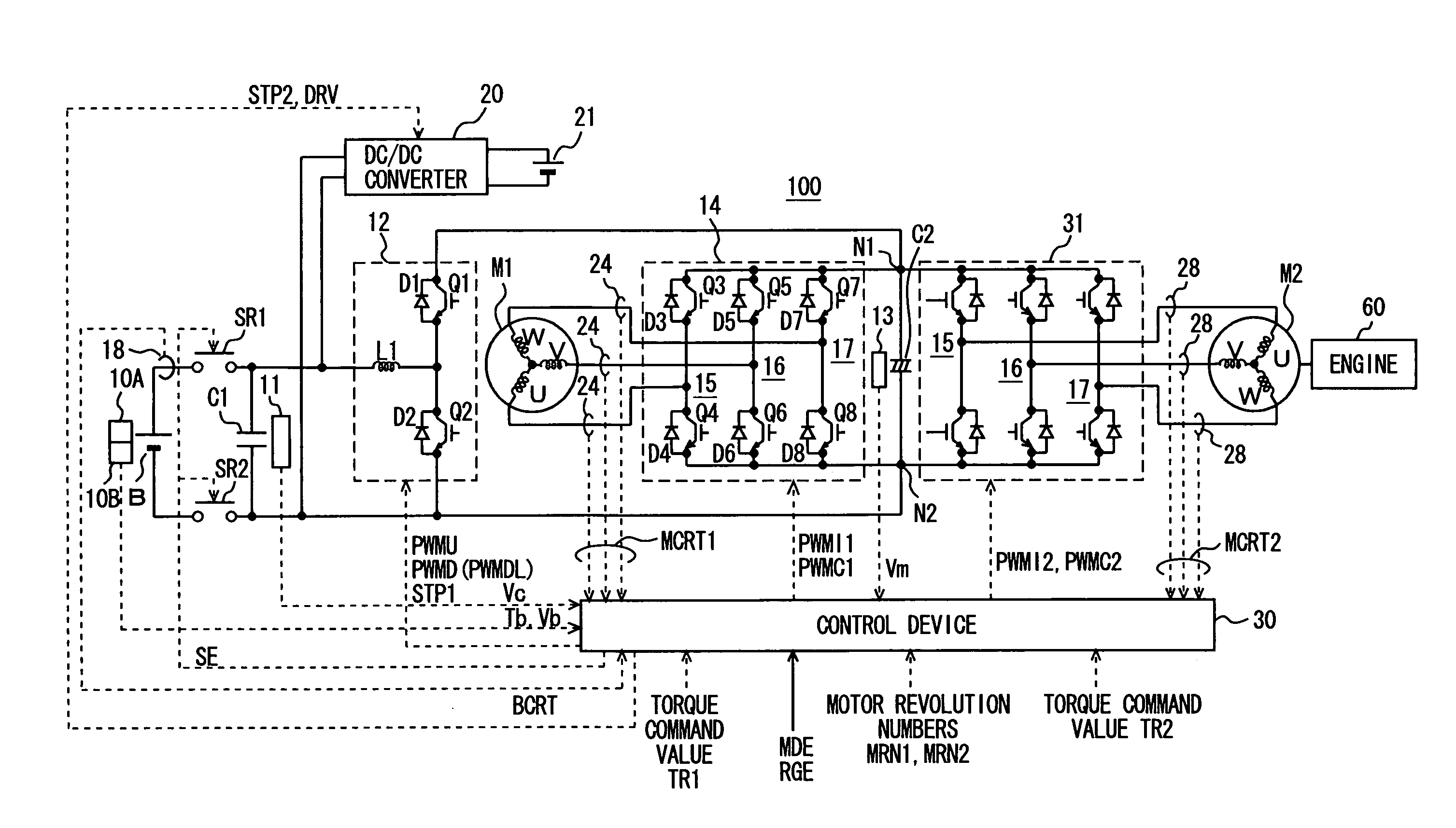
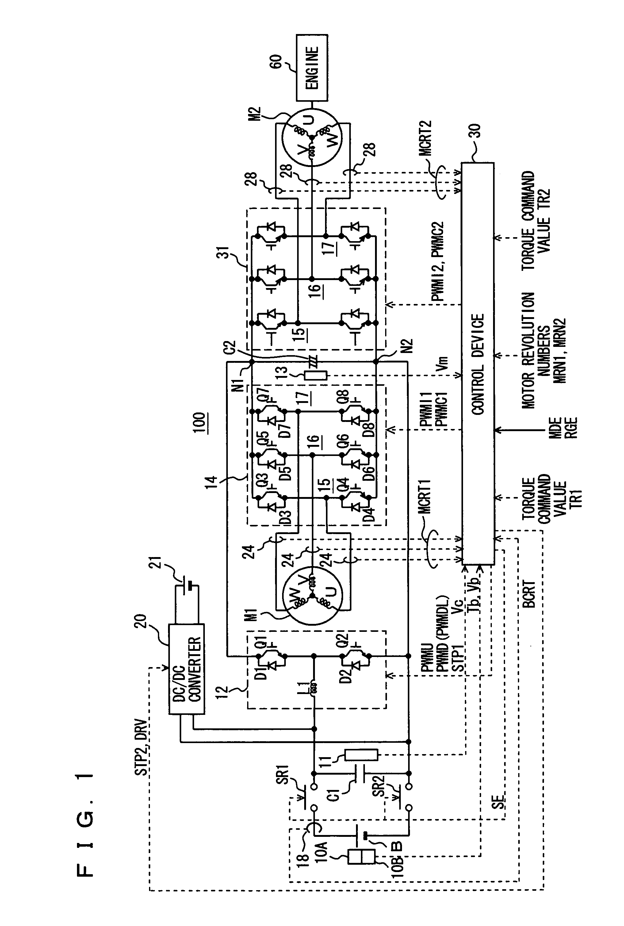
[0049]Referring to FIG. 1, a hybrid vehicle drive apparatus 100 mounted with a motor drive apparatus according to an embodiment of the present invention includes a DC power supply B, voltage sensors 10A, 11, 13, a temperature sensor 10B, system relays SR1, SR2, capacitors C1, C2, a voltage step-up converter 12, inverters 14, 31, current sensors 18, 24, 28, a DC / DC converter 20, an auxiliary battery 21, a control device 30, an engine 60, and AC motors M1, M2.

[0050]AC motor M1 is a drive motor for generating torque for driving drive wheels of the hybrid vehicle. AC motor M2 is a motor that can function as an electric power generator driven by the engine and also function as an electric motor for the engine to start the engine for ...


PUM


Abstract

Upon detection of a fault in a DC power supply based on a voltage from a voltage sensor or a temperature from a temperature sensor, a control device controls inverters to cause AC motors to output zero output torque, and generates and outputs signals to a voltage step-up converter and a DC / DC converter, respectively. The control device generates and outputs a signal SE of an L level to system relays to cut off the system relays. Thereafter, the control device generates and outputs a signal PWMDL to the voltage step-up converter to switch control of the voltage step-up converter to voltage step-down control.

Description

TECHNICAL FIELD[0001]The present invention relates to a motor drive apparatus driving a motor, a hybrid vehicle drive apparatus using the same, and a computer readable recording medium recorded with a program for causing a computer to perform control of the motor drive apparatus.BACKGROUND ART[0002]Hybrid vehicles have recently been of great interest as environment-friendly vehicles. Some hybrid vehicles have come into practical use.[0003]A hybrid vehicle includes, as its motive power sources, a DC (direct current) power supply, an inverter and a motor driven by the inverter, in addition to a conventional engine. Specifically, the engine is driven to generate motive power, and at the same time, a DC voltage from the DC power supply is converted to an AC (alternating current) voltage by the inverter to rotate the motor with the thus-converted AC voltage to thereby obtain motive power.[0004]For the hybrid vehicle, it has been studied to boost a DC voltage from the DC power supply with...

Claims


Application Information

Patent Timeline
Patent Type & Authority Patents(United States)
IPC IPC(8): B60K1/00B60K6/22B60K6/445B60L3/04B60L50/15B60L50/16B60W10/08B60W20/00H02P27/06
CPCB60W10/08B60K6/445B60L3/0046B60L3/0069B60L3/0092B60L3/04B60L11/123B60L11/14B60L15/20B60L2210/14Y02T10/7275B60L2240/36Y02T10/6217Y02T10/644Y02T10/646Y02T10/7077Y02T10/7216Y02T10/7225Y02T10/725B60L2210/10Y02T10/648Y02T10/6239B60L2210/20B60L50/16B60L50/61B60L58/10Y02T10/62Y02T10/64Y02T10/70Y02T10/7072Y02T10/72B60K6/20H02P27/05H02P27/06
Inventor SATO, EIJI
Owner TOYOTA JIDOSHA KK
Why Eureka
Try Eureka