
Computer system capable of fast failover upon failure

a computer system and failure technology, applied in the field of computer systems, can solve the problems of prolonging the time period during which the service is stopped, overriding the updated dns information by the cached dns information, etc., and achieve the effect of shortening the recorded time to live and increasing speed

Inactive Publication Date: 2006-08-29
HITACHI LTD
View PDF11 Cites 26 Cited by
  • Summary
  • Abstract
  • Description
  • Claims
  • Application Information

AI Technical Summary

Benefits of technology

The present invention provides a computer system that can quickly switch to a secondary site when there is a failure in the primary site. This is done by updating the DNS information in the DNS server to switch the site, but sometimes the cached DNS information can override the updated information. To solve this problem, the invention includes a primary request log processing unit that instructs the client to shorten the recorded time to live of the address information when communication with the secondary site is detected to be impossible. This helps to ensure that the service is only stopped for a brief period of time from a failure in the primary site. Overall, the invention improves failover speed and ensures continuous service availability.

Problems solved by technology

However, depending on the time to live (TTL) of the DNS information cache set on the Internet, the updated DNS information may be overridden by the cached DNS information.
The client accordingly accesses to the primary site and it takes time to redirect the client to the secondary site, thus prolonging the time period during which the service is stopped.

Method used


Image

  • Computer system capable of fast failover upon failure
  • Computer system capable of fast failover upon failure
  • Computer system capable of fast failover upon failure

Examples


Embodiment Construction

[0018]An embodiment of the present invention will be described below with reference to the accompanying drawings.

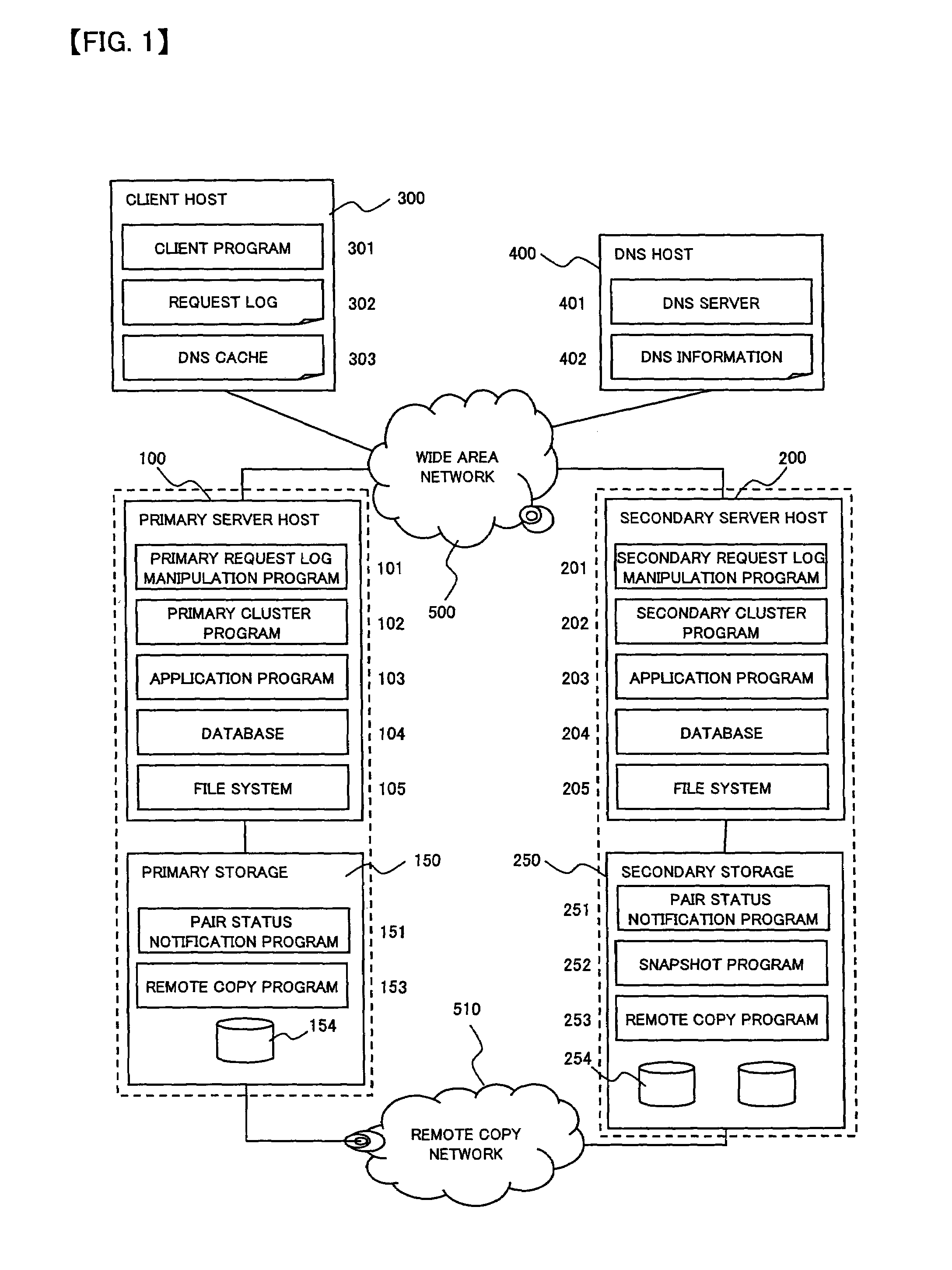
[0019]FIG. 1 is a block diagram showing the structure of a computer system according to the embodiment of the present invention.

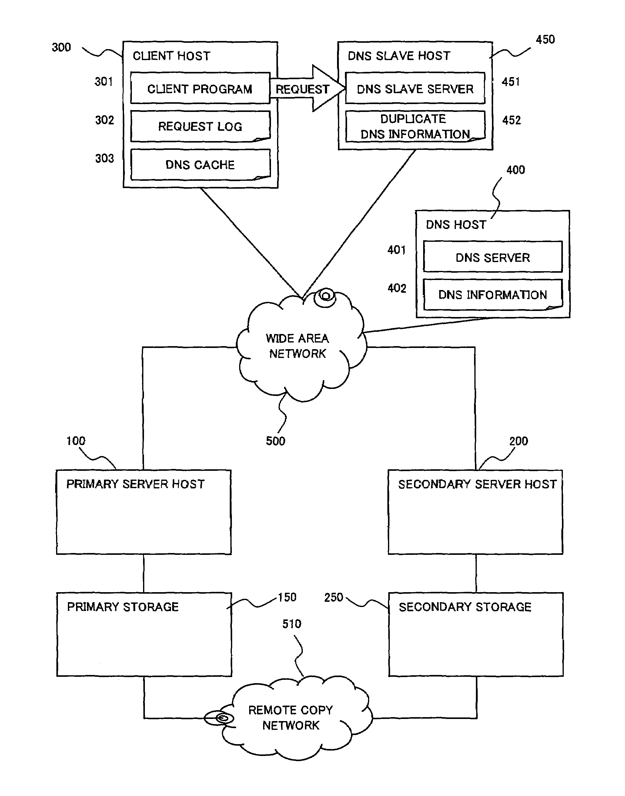
[0020]The computer system according to the present invention is composed of a primary server host 100, a primary storage 150 connected to the primary server host 100, a secondary server host 200, a secondary storage 250 connected to the secondary server host 200, a client host 300 which receives service provided from the primary server host 300, and a DNS host 400. The primary server host 100 and the primary storage 150 constitute a primary site for regular operation. The secondary server host 200 and the secondary storage 250 constitute a secondary site provided for operation when occurrence of a failure in the primary site.

[0021]The primary server host 100 is a computer device equipped with a CPU, a memory, a storage unit, and interfaces, and v...


PUM


Abstract

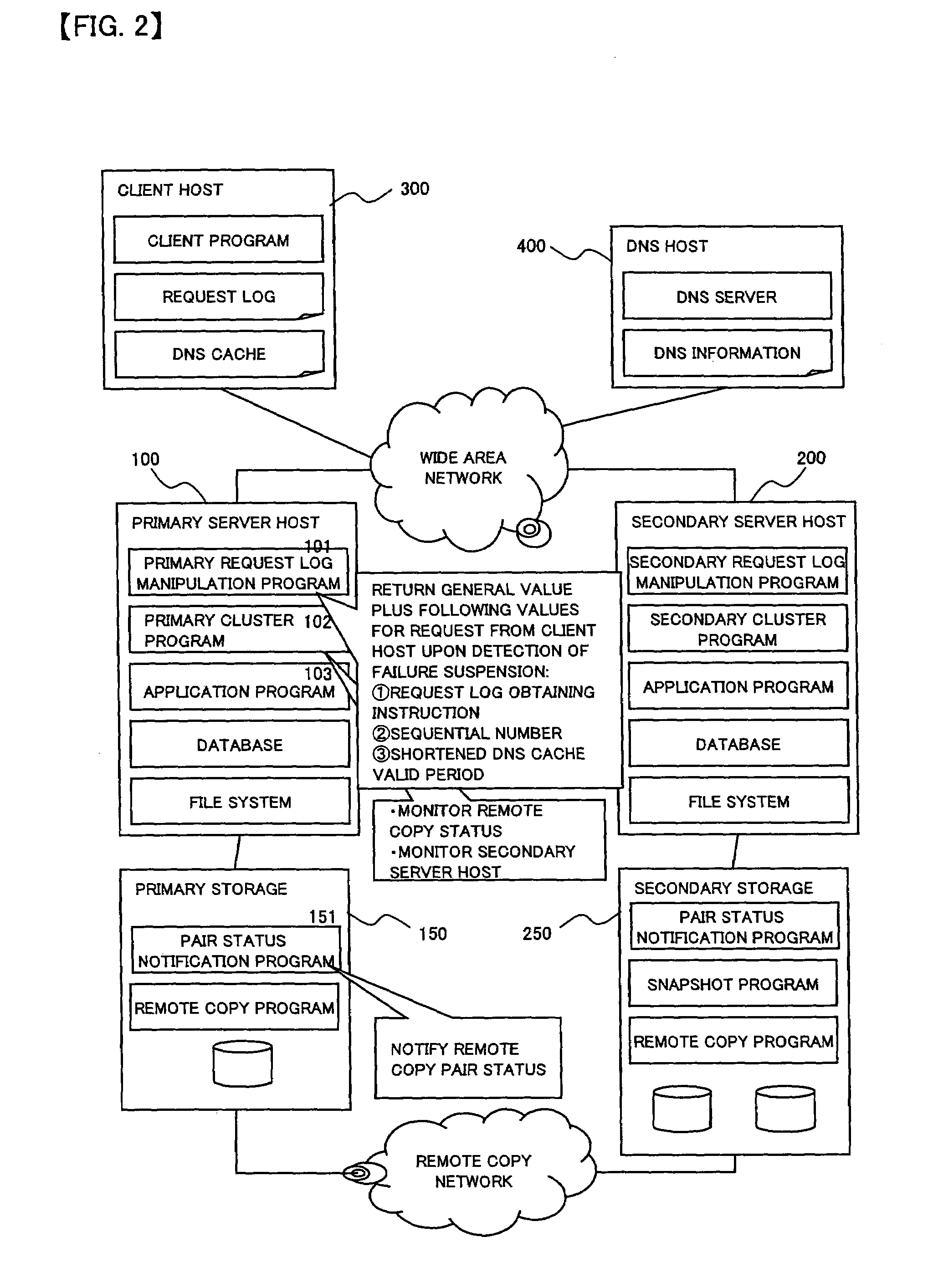
To provide a computer system capable of fast failover so that a service is stopped only for a brief period of time from a failure in a first site. The computer system includes a primary site for regular operation and a secondary site that operating when the primary site fails. A primary storage and a secondary storage have a synchronization unit to make contents stored in the primary storage and contents stored in the secondary storage identical to each other. A client has a cache for recording address information (e.g. DNS) that gives the client an access to the server from which the service is provided and information that defines a time to live of the address information. A first server has a primary request log processing unit, which instructs the client to shorten the recorded time to live of the address information when communication with the secondary site is detected to be impossible.

Description

BACKGROUND OF THE INVENTION[0001]The present invention relates to a computer system run on a primary site and a secondary site switching technique for when a failure takes place.[0002]There are many systems running in an information-driven society that provide services via the Internet, for example, a ticket reservation system and a network banking system. Many of such systems has two sites (a primary site and a secondary site) and keeps the secondary site on hot standby, so that switching is made quickly to the secondary site in case the primary site suffers a failure making the failure to stop the system only for a brief period of time (see JP 2002-312189 A, for example).[0003]The Internet has a DNS server for name resolution processing, which gives an IP address of a server accessed by a client. A cache of DNS information that gives the IP address is set on Internet, to thereby lighten the load of the DNS server and shorten the name resolution processing time (for example, see Re...

Claims


Application Information

Patent Timeline
Patent Type & Authority Patents(United States)
IPC IPC(8): G06F11/00G06F12/00G06F11/20H04L45/586H04L69/40
CPCH04L29/12066H04L61/1511H04L69/40H04L67/1034H04L67/1002H04L67/1029H04L61/4511H04L67/1001
Inventor IWAMURA, TAKASHIGEEGUCHI, YOSHIAKI
Owner HITACHI LTD
Learn More