
Method and apparatus for determining a site for an offshore wind turbine

a wind turbine and site technology, applied in the direction of electric generator control, vessel construction, instruments, etc., can solve the problems of data buoys being susceptible to damage, limited wind turbine placement, and expensive meteorological tower construction

Active Publication Date: 2006-09-05
GENERAL ELECTRIC CO
View PDF14 Cites 32 Cited by
  • Summary
  • Abstract
  • Description
  • Claims
  • Application Information

AI Technical Summary

Benefits of technology

"The patent describes a method and assembly for determining the best location for an offshore wind turbine. The method involves measuring conditions at multiple possible locations and using the data to determine the best site for the wind turbine. The assembly includes a floating support structure, a tower, and equipment for measuring wind conditions at the turbine's elevation above the water surface level. The counter-balance system is positioned below the center of gravity of the floating support structure to stabilize the turbine. The technical effects of this patent include improved accuracy in selecting the best location for offshore wind turbines and reduced costs associated with the assembly and installation process."

Problems solved by technology

However, placement of these wind farms is limited due to the desire to place the wind turbines in remote locations and the need to place the wind turbines in a location with favorable wind conditions to provide increased power output.
However, identifying favorable wind resource locations is a challenge to long term economic competitiveness and also a key for business development strategies.
However, these meteorological towers are expensive to construct and are stationary with respect to the sea floor.
However, these data buoys typically collect wind condition data at or near the water surface, which can be significantly different than the wind conditions at higher elevations, such as the elevation of conventional wind turbines.
Furthermore, these data buoys are susceptible to wave motion which can distort wind condition readings.
Accordingly, identification techniques of the kind presently in use have not previously provided wind condition measurements in a cost effective and reliable manner.

Method used


Image

  • Method and apparatus for determining a site for an offshore wind turbine
  • Method and apparatus for determining a site for an offshore wind turbine
  • Method and apparatus for determining a site for an offshore wind turbine

Examples


Embodiment Construction

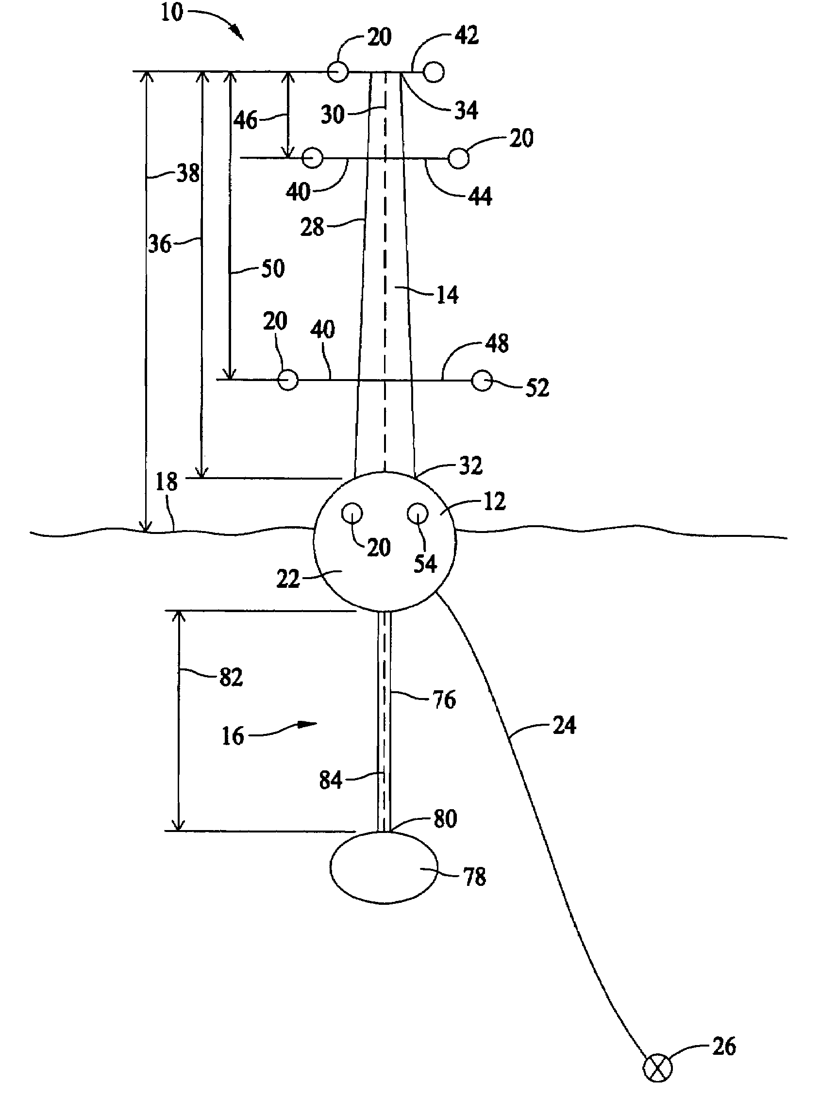
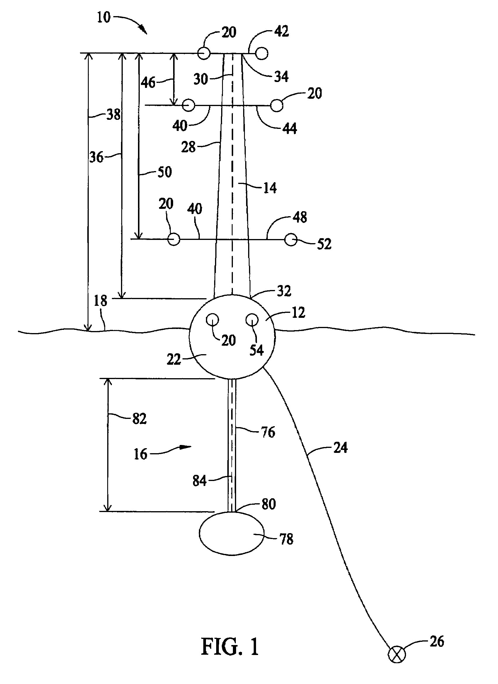
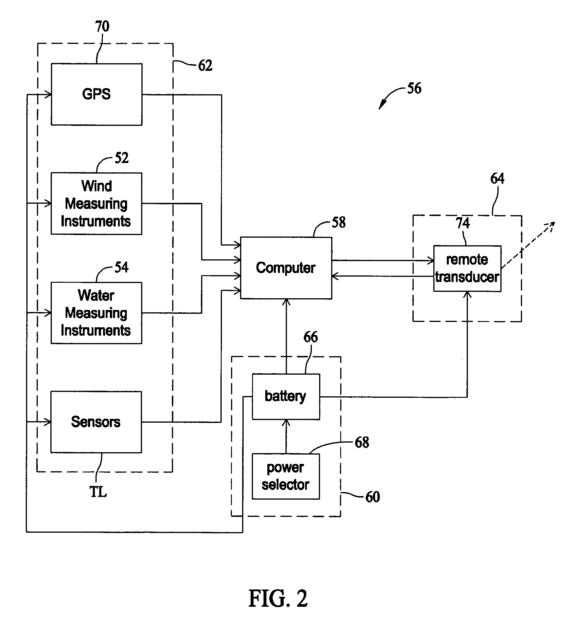
[0011]FIG. 1 is a side elevational view of a tower assembly 10. FIG. 2 is a block schematic diagram of tower assembly 10. Tower assembly 10 is used to determine a favorable site for an offshore wind turbine by measuring certain conditions, such as, for example, wind conditions and water conditions. Tower assembly 10 includes a floating support structure 12, a tower 14 extending upwardly from support structure 12, and a counter-balance system 16 coupled to support structure 12 for stabilizing tower 14 above a water surface 18. Equipment 20 is coupled to tower 14 for measuring the wind and water conditions.

[0012]Floating support structure 12 includes a buoy 22 for suspending tower 14 above water surface 18. In an alternative embodiment, a plurality of buoys 22 are provided for additional support and stability for tower assembly 10. The plurality of buoys 22 are coupled together to facilitate providing support to tower assembly 10, and in one embodiment have a triangular shape. Alterna...


PUM


Abstract

A method for determining a site for an offshore wind turbine includes determining a plurality of possible site locations, and positioning an offshore assembly at at least one of the possible site locations, wherein the assembly includes a floating support structure, a tower extending upwardly from the floating support structure, equipment coupled to the tower, and a counter-balance system coupled to the floating support structure at a location below a center of gravity of the floating support structure. The method further includes measuring conditions at the at least one of the possible site locations using the equipment, and determining a site for the offshore wind turbine from the at least one of the possible site locations based on the conditions of the plurality of possible site locations.

Description

BACKGROUND OF THE INVENTION[0001]This invention relates generally to offshore wind turbines, and more particularly to methods and apparatus for determining a site for an offshore wind turbine.[0002]Wind power is quickly becoming a growing energy source around the world. Conventionally, wind turbines are clustered together as wind farms in locations that have favorable wind conditions. However, placement of these wind farms is limited due to the desire to place the wind turbines in remote locations and the need to place the wind turbines in a location with favorable wind conditions to provide increased power output.[0003]Wind turbines are currently being sited at offshore locations. Offshore wind turbines are desirable because they provide additional locations to place wind turbines and they provide favorable wind conditions due to the lack of obstruction for wind currents. However, identifying favorable wind resource locations is a challenge to long term economic competitiveness and...

Claims


Application Information

Patent Timeline
Patent Type & Authority Patents(United States)
IPC IPC(8): G01M17/02
CPCB63B39/00F03D11/00Y02E10/722F05B2240/95F03D80/00B63B1/047B63B35/44B63B2035/446Y02E10/727F03D13/25Y02E10/72
Inventor LEMIEUX, DAVID LAWRENCE
Owner GENERAL ELECTRIC CO
Learn More